Heating stoves
Heating stoves differ in the duration of combustion (short-term or long burning), the amount of heat transfer and the degree of heating (moderate and increased).
Moderately heated ovens, as a rule, have walls at least half a brick thick. They warm up slowly during combustion and retain heat for a long time, but also cool down slowly. With one or two fires per day, a uniform air temperature is maintained in the room. On their surface, the temperature of maximum heating is on average no more than 55-60°C, and at some points - 85-90°C. All this eliminates dust burning and improves hygienic conditions in the room. Stoves are widespread in the northern and middle zones of our country. Their service life is 30-40 years. Such furnaces have some disadvantages: they are large, require a solid foundation and a large amount of various materials, and occupy a fairly large area.
High-heat furnaces have thinner walls, a quarter of a brick is poured. They warm up and cool down faster, the temperature on their surface averages 65-75°C, and at some points reaches 120°C. At this temperature, dust begins to burn on them, producing bad smell. In addition, they do not maintain a uniform temperature in the room and are thus inferior to thick-walled stoves (moderate heating). Basically, in these furnaces, only the fireboxes are made with walls half a brick thick, the rest of the furnace is made of a quarter of a brick. Such ovens take up less space and require less material and funds.
Furnaces in plan form are square or rectangular, round and angular (triangular). Square and rectangular stoves are simpler to install. Round stoves, which are more attractive in appearance, are always placed in metal cases. Corner stoves are conveniently placed in the corners of the room.
According to the smoke circulation system, they are multi-turn, in which vertical and horizontal channels with a large number of turns are located sequentially. They can be single- and double-turn, with one or several lower channels located in parallel, as well as channelless or bell-type, with bottom heating and a combined smoke circulation system.
Smoke is discharged through root or manifold pipes or through wall smoke ducts.
These stoves can be brick, tiled, metal cased, smooth or corrugated steel, or metal frame unfinished or lined with asbestos plywood sheets, sheet steel or glazed parts. In addition to stoves made of brick, there are block stoves made of ceramics or heat-resistant concrete. These ovens are easy and quick to assemble.
Furnaces are made single-story and multi-story. Depending on the design and purpose, stoves come with a regular (periodic) combustion mode and slow or continuous combustion. In the latest furnaces, the combustion process is extended in time or occurs continuously. Because of this, the surface of the oven does not cool down.
Many of the furnaces under consideration have a thermal characteristic with two fireboxes per day for each furnace wall separately. This is done because not all of them heat up equally. In some ovens, the front and back walls heat up almost half as much as the right and left ones. It happens that the front wall heats up much more than the rest.
Heating stoves are plastered after complete drying and settling of the masonry. In this case, the seams are selected to a depth of at least 1 cm. The solution is applied to the hot walls of the oven.
This section discusses the laying of the first furnace in more detail, the rest are described more briefly. Thus, the first furnace must be worked out very thoroughly.
Plastered stove with heat output 1760 kcal/h
The heating stove (Fig. 74) has dimensions: width - 510 mm, length - 770, height - 2150 mm. The front and back walls account for 340 kcal/h, the left and right walls - 540 kcal/h.
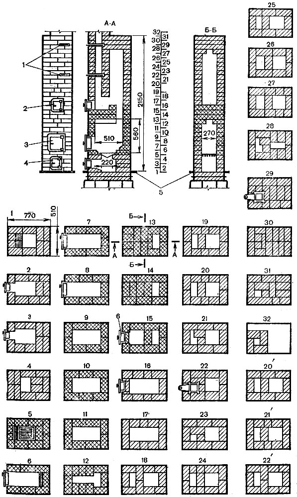
Materials: ordinary brick - 210 pieces; refractory brick - 76 pieces; ordinary clay - seven buckets; refractory clay - 23 kg; sand - 3.5 buckets; grate - 252×250 mm; combustion door - 250×205 mm; blower door - 130×140 mm; cleaning door - 130×140 mm; two smoke valves - 130×130 mm; pre-furnace sheet - 500×700 mm; 2 m of waterproofing (roofing felt) - 800×550 mm. Refractory brick, shaded with cells, can be replaced with ordinary selected brick.
The first row is made rectangular strictly in size, with a device in the middle of the masonry ash pit measuring 260x260 mm. On the left side of the order, the brick is cut off (see section A-A), which ensures easier removal of ash.
In the second row, install the blower door, resting it on the first row and carefully securing it.
The third row is similar to the second, only the order of laying the bricks is changed, which ensures that the seams are bandaged.
The fourth row covers the blower door and reduces the size of the hole above the blower to 260x200 mm, on which the grate is laid in the next row.
In the fifth row, a grate is first laid over the hole in the fourth row, then the masonry is made so that between the grate and the masonry there is a gap of at least 10 mm around the entire perimeter, necessary for the expansion of the heated metal. The brick on the side of the combustion door (on the left side) is cut off at the end so that the fuel rolls onto the grate and burns normally.
During the laying process, pay attention to the order.
The sixth row forms a firebox. The brick on the back side of the firebox is cut off. The combustion door is installed and secured on the front side.
The seventh and eighth rows are the same, except for the seam dressing. If in the sixth row the back wall of the stove (firebox) was laid out three-quarters of a brick thick, then in these rows it is laid in half a brick.
The ninth - eleventh rows are exactly the same, with the exception of dressing the seams. The ninth row covers the combustion door.
The twelfth row is laid according to the order in which eight three-fours and one half of a brick are used. This masonry narrows the firebox, which is necessary to cover it in the next row. In this order, it resembles the letter T.
The thirteenth and fourteenth rows are the same, except for the binding of the seams. On their right side there is only one channel left, the rest is blocked.
In the fifteenth row, the same channel remains on the right side, and on the left, cleaning is done by installing a door in the fourteenth row opposite the pipe channel.
The sixteenth and seventeenth rows are similar, only the seventeenth row overlaps the cleaning door, leaving a rectangular horizontal channel in it.
The eighteenth - twentieth rows are laid in the same way, but with observance of ligation of the seams, dividing the large channel into two. The channel on the left side measuring 260x130 mm is directed into the pipe.
The twenty-first row is placed so that the left channel is overlapped by the three-four, reducing it by 1/4. This is necessary to further hold the brick covering half of the channel.
The twenty-second row covers half of the channel on the left side of the furnace, and a valve is installed on the remaining half.
The twenty-third row is placed in order, forming a channel measuring 130x130 mm above the valve.
From the twenty-fourth to the twenty-seventh row inclusive, the masonry is performed in the same way, only with the observance of dressing the seams.
On the left side of the furnace, the channel expands to a size of 260x130 mm. The channel on the right side, starting from the eighteenth row, remains unchanged with a size of 260x260 mm.
The twenty-eighth row is similar to the twenty-first row, only the channel on the right side is reduced to a size of 260x130 mm.
The twenty-ninth row covers the top of the furnace, and a second valve is placed on it.
The thirtieth and thirty-first rows also cover the top of the furnace, leaving the pipe channel and observing the ligation of the seams.
The thirty-second row shows the laying of a pipe in four bricks with a channel size of 130x130 mm.
If the room is 2.7 m high, then three rows should be inserted between the nineteenth and twentieth rows: 20", 21" and 22", observing the ligation of the seams.
Having folded the stove, they begin to lay the pipes, strictly observing the dressing of seams and fire safety measures when passing through the attic floor and roof.
Plastered stove with heat output 1940 kcal/h
The heating stove (Fig. 75) has dimensions: width - 510 mm, length - 890, height - 2150 mm. The front and back walls account for 335 kcal/hour, and the right and left walls account for 635 kcal/hour.
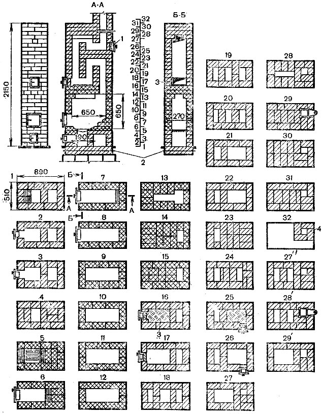
Rice. 75. Heating stove, plastered, with heat output 1940 kcal/h: 1 - cleaning; 2 - waterproofing; 3 - layer of clay-sand mortar; 4 - mounted pipe with channel 140×140 mm
Materials: ordinary brick - 245 pieces; refractory brick 110 pieces; ordinary clay - eight buckets: refractory clay - 11 kg; sand - seven buckets; grate - 252×250 mm; combustion door - 250×205 mm; blower grill - 130×140 mm; two cleaning doors - 130×140 mm; two smoke valves - 130×130 mm; pre-furnace sheet - 500×700 mm; 2 m of waterproofing (roofing felt) - 1000×1000 mm. Refractory brick is shaded with cells. It can be replaced with selected ordinary bricks. Since the previous oven was described in detail, this one, which is in many ways similar to it, will be discussed more briefly.
The first, fifth, sixth and seventh rows shaded in the figure show that the brick inside the channels and on both sides of the grate is cut off (section A-A). The thirteenth row overlaps the previously made firebox in the form of a rectangle so that a channel in the form remains above it letter T. Subsequently, it is narrowed and reduced to a size of 130 × 260 mm. In the sixteenth and twenty-fifth rows, the brick planes are leveled by laying 10 mm of clay-sand mortar on them, thereby making them smoother, which makes it easier to remove soot.
The pipe channel is laid in four bricks measuring 130x130 or 140x140 mm, which depends on the thickness of the seams. The firebox is designed for firewood. In rooms with a height of 2.7 m, rows 27", 28" and 29" are inserted between the twenty-sixth and twenty-seventh rows.
The design of this furnace was proposed by V.I. Strezhnev.
Plastered stove with heat output 2400 kcal/h
The heating stove (Fig. 76) has dimensions: width - 510 mm, length - 1400, height - 2150 mm. The front and back walls account for 280 kcal/hour, and the right and left walls account for 920 kcal/hour.

Materials: ordinary brick - 380 pieces; refractory brick - 190 pieces; ordinary clay - eleven buckets; refractory clay - 57 kg; sand - ten buckets; grate 250×252 mm; combustion door - 250×205 mm; blower door 130×140 mm; two cleaning doors - 130×140 mm; two smoke valves - 130×130 mm; pre-furnace sheet - 500×700 mm; waterproofing (roofing felt) - 1450×550 mm (2 sq. m).
The laying is carried out according to the procedures, with careful bandaging of the seams. Refractory brick can be replaced with good ordinary brick. If shading is shown inside the channels, this indicates hewn brick. You should carefully familiarize yourself with the sections of the stove.
From the twentieth to twenty-fifth rows inside the channels large sizes half the brick is laid, which is necessary for installing partitions in the upper part of the furnace. From the thirty-second row, the laying of a pipe of five bricks begins, the channel size is 130 × 260 mm.
For rooms with a height of 2.7 m, 24" 25" and 26" rows must be inserted between the twenty-third and twenty-fourth rows.
Plastered stove with heat output 3020 kcal/h
The heating stove (Fig. 77) has dimensions: width - 770 mm, length - 1020, height - 2150 mm. The front and back walls account for 610 kcal/hour, and the right and left walls account for 900 kcal/hour.
Materials: ordinary brick - 400 pieces; refractory brick - 220 pieces; ordinary clay - thirteen buckets; refractory clay - 66 kg; sand - ten buckets; grate - 250×180 mm; combustion door - 200×205 mm; blower door - 130×140 mm; two cleaning doors - 130×140 mm; two valves - 240×130 mm; pre-furnace sheet - 500×700 mm; waterproofing (roofing paper) - 770×1020 mm (2 sq. m). The laying of the stove is carried out according to the procedures, with careful bandaging of the seams. Refractory brick can be replaced with ordinary selected brick. In the fifth and sixth rows, the brick is cut off, as evidenced by the shading in the picture inside the firebox and near the grate. To close the oven, two valves are installed (see rows 25 and 29). The pipe is placed in five bricks with a channel 130x260 mm.
For rooms with a height of 2.7 m, between the twenty-sixth and twenty-seventh rows, it is necessary to insert 27", 28" and 29" rows.
Plastered stove with heat output 3850 kcal/h
The heating stove (Fig. 78) has dimensions: width - 1020 mm, length - 1020, height - 2150 mm. The front wall accounts for 1000 kcal/h, and the rest - 950 kcal/h.

Materials: ordinary brick - 552 pieces; refractory brick - 206 pieces; ordinary clay - fourteen buckets; refractory clay - 91 kg; sand - thirteen buckets; grate - 252×300 mm; combustion door - 250×205 mm; blower door - 250×140 mm; five cleaning doors - 130×140 mm; two smoke valves - 240×130 mm; pre-furnace sheet - 500×700 mm; waterproofing (roofing paper) (2 sq. m).
The laying of the stove is carried out according to the procedures, with careful bandaging of the seams. Refractory brick can be replaced with selected ordinary brick.
From section A-A it can be seen that the front and back walls are made of refractory brick 3/4 (19 cm) thick. One row of masonry is laid flat, the other - on the edge, with a thickened seam. If it is possible to line (cover) the firebox with refractory brick, then it is placed on the edge. The walls are made of ordinary bricks in exactly the same order. It should be remembered that the use of thickened refractory brick masonry is associated with high temperature in a firebox, which quickly destroys ordinary bricks.
Almost half of the furnace is made of refractory brick. Valves are installed in the twenty-fifth and twenty-ninth rows. For rooms with a height of 2.7 m, between the twenty-sixth and twenty-seventh rows, two more rows of masonry of the twenty-fifth and one twenty-sixth row are inserted. The pipe is made of five bricks with a channel of 130×260 mm.
Oven in a metal case with a heat output of 3920 kcal/h
The heating stove (Fig. 79) has dimensions: width - 890 mm, length - 1140, height - 2150 mm. The heat transfer for each wall is not indicated.

Materials: ordinary brick - 400 pieces; refractory brick - 253 pieces; ordinary clay - thirteen buckets; refractory clay - 110 kg; sand - twelve buckets; combustion door - 250×205 mm; blower door - 250×140 mm; five cleaning half-doors - 130×160 mm; two smoke valves - 240×130 mm; grate - 300×252 mm; pre-furnace sheet - 500×700 mm, roofing steel for the case 10 sq. m, only 2 sq. m for waterproofing.
After making the case, it is coated with fire-resistant varnish on the inside and outside. The case consists of several links. The lower, or first, link is made no more than 700 mm high. At a higher height, it is very inconvenient to work in it when laying the first rows. The case must be carefully marked and equipped with places for the blower, doors, cleaning, and latches. On the inside of the case, 6-10 clamps made of strip steel are placed to secure the case to the furnace body. The front and rear walls are laid in half, and the side walls in a quarter of a brick.
The first row is laid first and a case is put on it, or the case is placed first, and then the laying is done. The brick should adhere to the case as tightly as possible and, best of all, on a layer of clay mortar, since the air gap between the case and the masonry greatly reduces heat transfer. The masonry is carried out according to the order, with bricks being cut in the required rows. As soon as the first link is filled with masonry, the second is put on it and placed further, etc. The pipe is placed in a five-piece with a channel of 260x130 mm. For rooms with a height of 2.7 m, 27", 28" and 29" rows must be inserted between the twenty-sixth and twenty-seventh rows.
Tiled stove with heat output 4150 kcal/h
The heating stove (Fig. 80) has dimensions: width - 1020 mm, length - 1020, height - 2150 mm. The heat transfer for each wall is not indicated.
![]()
Materials: ordinary brick - 425 pieces; refractory brick - 155 pieces; ordinary clay - fourteen buckets; refractory clay with fireclay - 75 kg; sand - thirteen buckets; combustion door - 250×205 mm; blower door - 250×140 mm; six cleaning doors - 130×140 mm; two smoke valves - 240×130 mm; grate - 300×252 mm; pre-furnace sheet - 500×700 mm; terracotta corner tiles - 52 pieces, straight tiles - 162 pieces, roofing felt for waterproofing - 2 sq. m.
Before laying the stove, the tiles are sorted by color and size, individual inaccuracies are sharpened, and the bricks are sorted. First of all, each row is laid without mortar, corrected, disassembled and then sequentially laid on mortar.
The tiles are fixed in the masonry as described earlier. The masonry is carried out strictly according to the order, with careful dressing of the seams. The pipe is placed in five bricks with a channel 260x130 mm.
For rooms with a height of 2.7 m, 27", 28" and 29" rows are inserted between the twenty-sixth and twenty-seventh rows.
After laying, the front surfaces are cleaned of dust and dirt, the seams between the tiles, depending on the color, are filled with white or tinted gypsum mortar.
*** To view drawings, click on the picture
Rectangular heating stove with increased heat output. For heating large rooms, it is recommended to install rectangular stoves with increased heat output. The oven, like the one described above, is simple in design. An idea of her design features gives rice 2.3.2, which shows the facade and vertical section of the furnace.
The firebox design is the same as that of the 0-2 Giproaviaprom stove. It can burn any solid fuel. The flue gases from the firebox rise through the vertical channel, but do not reach the furnace roof, but, having been reflected from the intermediate ceiling, fall to the bottom of the furnace, where through the underpass they enter the rear lifting channel, along which they rise to the furnace roof. After then passing through a series of successive revolutions, the gases escape into the chimney. The oven has bottom heating. Due to the large area of the heated outer walls, the heat transfer of the furnace with two fireboxes per day is 6400 W.
Smoke valves are installed on the 32nd and 36th rows. The second valve is not shown in the drawing. The cross-section of the chimney channel is above the horizontal groove (13x13 cm).
For laying the furnace it is required:
- Ordinary brick - 578 pcs.
- Blower door 14x25 cm - 1 pc.
- Fire door 26x27 cm - 1 pc.
- Cleaning doors 13x14 cm - 3 pcs.
- Viewing valves 25x13 cm - 2 pcs.
- Ordinary clay - 0.45 m 3
- Sand - 0.45 m 3
- Roofing felt for waterproofing - 3 m

For laying the furnace it is required:
- Red brick - 490 pcs.
- Grate 25x25 cm - 1 pc.
- Fire door 28x27 cm - .1 pc.
- Blower door 14x13 cm - 1 pc.
- Cleaning door 14x13 cm - 1 pc.
- Viewing valve 25x13 cm - 1 pc.
- Furnace wire Ø2 mm. - 3 m
- Ordinary clay - 0.4 m 3
- Sand - 0.4 m3
- Pre-furnace sheet 70x50 cm - 1 pc.
- Roofing felt for waterproofing - 3 m 2
The furnace is laid in the following order (see Fig. 2.3.4 - 2.3.6).
1st row. The bottom of the ash pan is formed in the front part. The brick lying in the blower door is beveled.
2nd row. They install a blower door. A channel is formed in the rear part, which is closed on one side with a blank wall and on the other with a cleaning door.
3rd row. The bricks in the front protruding part are laid out in such a way that when laying the next row, the vertical seams are tied.
4th row. The walls of the ash chamber in this row are 18 cm thick. Increasing the thickness of the walls is necessary so that after laying the grate there are no gaps between its edges and the walls of the firebox. In the rear part, cuts begin that separate the lifting vertical channels.
5th row. Lay the grate.
6. 7, 8 and 9th rows. In the front part, a firebox with a plan size of 26x51 cm is laid out. On the 8th and 9th rows, the firebox is connected to the fire chamber.
10th row. Cover above the fire door.
11,12 and 13th rows. Firebox shut-off device at outlets. In the rear part there is a continuation of the laying of the fire chamber and lifting channels.
14th row. A cleaning door is installed on the façade side. An upper chamber is formed in the front part. Support post size. 1/2x1/2 brick divides it into the chamber itself, connecting channels and the base of the chimney.
15, 16, 17th rows. The masonry of these rows differs from the previous one only in the arrangement of bricks for bandaging the vertical seams.
18,19,20, 21st rows. The base of the cut is applied through the support column between the upper chamber and the chimney. Otherwise the masonry is the same as the previous rows.
22nd and 23rd rows. Cover the lower heating chamber.
24th and 25th rows. Vertical lifting channels are connected to the upper chamber through a channel. Install a cleaning door to clean the horizontal channel.
26, 27, 28 and 29th rows. Overlap device. On the 28th row a view gate is installed. Starting from the 30th row, lay a chimney with an internal channel of 25x13 cm.
As mentioned above, there are several types of stoves: heating, for cooking, and those combining both of these functions. In addition to stoves, there are fireplaces, but they are rarely used for cooking, and are mainly of a heating and decorative nature: they are sources of heat and create comfort in the room.
Heating and heating-cooking furnaces
Heating stoves differ in the duration of the firebox (short-term or long-term burning), heat transfer and degree of heating (moderate or increased). Moderate heating stoves have walls at least 1/2 brick thick, they warm up slowly during combustion and retain heat for a long time (with one or two fires per day, they maintain an almost constant air temperature in the room).
Their surface is heated to a temperature of no more than 55–60° C, in some places - up to 85–90° C. This prevents dust from burning on the surface of the oven and improves hygienic conditions in the room. Laying such furnaces requires a large amount of material and a solid foundation.
Furnaces with increased heating have thinner walls - half a brick or a quarter of a brick. They warm up quickly and cool down just as quickly. The temperature of these ovens is on average 65–75° C, and in some places reaches 120° C. Dust often burns on them, emitting an unpleasant odor. These stoves do not maintain a uniform temperature in the room and are therefore inferior to moderate heating stoves. Their construction requires less material; Usually in such stoves the firebox and the lower part of the stove are laid out in half a brick, and the rest - in a quarter of a brick.
The heat output of heating stoves ranges from 1300 to 4000 kcal/h. It must, however, be remembered that heating the room and maintaining a normal constant temperature in it at stove heating depends not only on the heat transfer of the furnace (although this is a determining factor), but also on thermal insulation properties the premises (house) itself.
Furnace designed by V.E. Grum-Grizhimailo
The operation of the furnace is based on the design of V.E. Grum-Grizhimailo (Fig. 45) lies the principle of free movement of gases. The firebox of this stove is located at the bottom; through the firebox in the middle part of the stove, gases enter the bell from the firebox, where they transfer some of the heat to the ceilings and walls of the stove. As the gases cool, they become heavier and under the influence own strength weights are lowered through the empty space near the walls of the furnace into a horizontal horseshoe-shaped smoke channel, which, in turn, is connected to the chimney.
Rice. 45. Furnace designed by V.E. Grum-Grizhimailo. Device. Masonry sequence
Furnace designed by V.E. Groom-Grizhimailo retains heat well and does not cool down even if the ventilation valve is closed, since the cold air entering the firebox through the blower door is heavier than that in the hood. Cold air remains in the lower part of the furnace without reducing the heating of the upper part of the structure. This property of the furnace is called gas view.
Materials
Brick - 260 pcs.;
Fire-resistant brick - 65 pcs.;
Fireproof clay - 11 kg;
Roofing steel (for the case) - 6.5 m2;
Sand - 0.037 m3;
Pre-furnace sheet made of roofing steel - 50 x 70 mm;
Roofing felt for waterproofing 850 mm wide - 2 sheets.
Rectangular heating stove (1)
Device (Fig. 46, a)
This oven has dimensions of 510 x 890 x 2380 mm. The furnace firebox is located in its lower part, and its walls are also the walls of the furnace, due to which predominantly bottom heating is achieved.
Rice. 46. Rectangular heating stove, model 1: a - device; b - masonry sequence
Materials
Ordinary brick - 245 pcs.;
Fireproof brick - 110 pcs.;
Ordinary clay - 0.2 m3;
Fireclay clay - 12 kg;
Sand - 0.2 m3;
Fire door 250 x 200 mm - 1 pc.;
Blower door 130 x 140 mm - 1 pc.;
Cleaning door 130 x 140 mm - 2 pcs.;
Viewing valve 130 x 130 mm - 2 pcs.;
Roofing felt for waterproofing - 100 m2.
Sequence of masonry (Fig. 46, b)
1st row - three-quarter bricks are placed in the corners, the front wall is laid out with pokes. Two middle bricks are cut along the upper edges, making a slope towards the bottom of the ash pit (cut AA). The space between the rear wall of the ash pan and outer wall The furnaces are covered with dry sand up to the 3rd row inclusive.
2nd row - install a blower door in the center of the front wall, place three-quarter bricks on the sides of it, then lay a layer of full-size bricks.
3rd row - building up the masonry. When all the bricks have been laid, a 4 x 35 cm steel strip is placed over the front of the ash pit.
4th row - the ash chamber overlap is placed on the steel strip. At the rear, the top of the sand backfill is covered with bricks.
5th row - install a grate over the ash pit. The bricks located in front and behind it are cut so that a bevel is obtained for rolling the coals onto the grate.
6th row - install the furnace door. They are cutting off the bricks back wall so that their slopes are in the same inclined plane with the slopes of the bricks of the previous row.
Rows 7–12 - laying a firebox in 1/2 brick with mandatory bandaging of the seams.
13th row - outlets for covering the firebox on the front wall and part of the side ones. They are laid out from three-quarters.
The 14th and 15th rows are the floor masonry above the fuel chamber. A hole is left in the rear part, which serves to connect the firebox to the vertical channel.
16th row - installation of the cleaning door. On the right, the door rests on 1/2 of a brick placed on its edge. To isolate the firebox from the smoke channels above, the shelf behind the door is covered with clay cement mortar.
17th–20th rows - vertical ones are placed smoke channels.
21st and 22nd rows - the lifting and lowering channels are connected to each other. This is where the cut ends, separating the posterior ascending canal and the middle descending canal.
23rd and 24th rows - laying the overlap of the rear and middle channels.
25th and 26th rows - installation of a cleaning door. Tuck from the middle channel of the second tier to the chimney.
The 27th row is the beginning of laying the smoke channels of the second tier.
28th row - installation of a view valve.
Rows 29–30 - laying smoke ducts of the second tier.
Row 31 - laying outlets to cover the furnace.
The 32nd row is the beginning of laying the furnace roof; it is carried out with the obligatory bandaging of the seams. To reduce heat transfer loss, install a second view valve.
The 33rd and 34th rows are the laying of the furnace roof.
Rectangular oven (2)
Device
In its design, this stove is similar to the previous one, however, it has increased heat transfer, thanks to which it can heat rooms of a larger area.
It is also equipped with a bottom heating system; it can burn any type of fuel.
Materials
Ordinary brick - 578 pcs.;
Ordinary clay - 0.5 m3;
Sand - 0.5 m3;
Blower door 140 x 250 mm - 1 pc.;
Fire door 260 x 270 mm - 1 pc.;
Cleaning door 130 x 140 mm - 3 pcs.;
View valve 250 x 130 mm - 2 pcs.;
Grate 250 x 250 mm - 1 pc.;
Roofing felt for waterproofing - 3 m2.
Sequence of masonry (Fig. 47)
Rice. 47. Rectangular stove, design 2. Sequence of masonry
The masonry is the same as in the first version of the rectangular heating stove, except for the 32nd and 36th rows. View valves are placed on them.
Russian stove
Device
As already mentioned in the chapter devoted to the design of stoves, the Russian stove, in addition to a number of advantages, also has the disadvantage of preferentially heating only the upper layers of air. However, it still remains one of the most popular types of stoves that combine heating and cooking functions.
The components of an ordinary Russian stove are shown in rice. 48.
Rice. 48. Components of a Russian stove: a - oven; b - niche; c - sixth; g - crucible; d - choke; e - shield; g - valves; h - chimney; and - roof of the furnace
Materials
Russian stoves come in large, medium and small. Here we will consider the construction option small oven, having dimensions 1270 x 650 x 2380 mm. For it you will need the following materials:
Ordinary brick - 1610 pcs.;
Clay solution - 1200 l;
Damper made of sheet steel 430 x 340 mm - 1 pc.;
Viewing valve 300 x 300 mm - 2 pcs.;
Samovar 140 x 140 mm - 1 pc.
Sequence of masonry (Fig. 49)
Rice. 49. Russian stove. Masonry sequence
1st row - laying out the baking area. The masonry is carried out mainly from whole bricks on a mortar intended for the foundation.
Rows 2–4 - laying a well with mandatory bandaging of the seams. On one side you need to leave a hole for baking.
5th row - the beginning of laying the vault above the oven. The side rows are laid out with heels to support the arch, and formwork is built on them.
The 6th and 7th rows are the vault covering the under-bowl.
8th row - vault lock.
The 9th and 10th rows are laid in one brick.
11th row - laying out the ceiling of the “cold stove” located above the oven. The space inside the masonry is filled and leveled with a slope from the back wall of the cooking chamber to the hearth.
The 12th row is the laying of the hearth, which, as a rule, is made from special hearth bricks. The underneath is sprinkled with fine-grained sand and leveled with bricks.
The 13th row is the first row of the cooking chamber, laid out in 3/4 bricks. The corner bricks of the front wall must be cut at an angle of 45° and secured into a lock. In this row, the masonry is not bonded; bandaging the seams is required.
Rows 14–16 - place in the same way as row 13.
17th row - laying the roof of the mouth and laying the heels under the roof of the cooking chamber. To lay the heels, hewn bricks placed on edge are used.
18th row - laying the walls of the stove and stoves. As alternative option you can fill the space between the roof of the cooking chamber and the walls with sand or clay mortar with brick crushed stone as filler.
19th row - laying out the walls of the vault, arranging an arched ceiling for the hole above the pole.
20th row - using chopped brick, reduce the hole above the pole (overpipe), and also make an overlap above the channel for the samovar.
21st row - leveling the walls and reducing the overlap.
22nd row - reducing the overtube. Laying the samovar channel. The brick on the right side of the beam is cut off, and the masonry above the arch is leveled. Lay out the soot box.
23rd row - a samovar is arranged, which is closed with a lid.
Rows 24–32 - install view valves.
From the 32nd row, the laying of a pipe with a smoke channel cross-section of 2 bricks begins.
Country stove
Below is an example of the masonry of a relatively simple, small-sized stove: width - 510 mm, length - 770 mm, height - 2150 mm, with a heat output of 1760 kcal/h (Fig. 50, 51).
Rice. 50. Country stove. Device: 1 - waterproofing; 2 - blower; 3 - firebox; 4 - cleaning; 5 - valves
Rice. 51. Country stove. Masonry sequence
Rice. 51 (continued). Country stove. Masonry sequence
Materials:
Ordinary brick (red) - 210 pcs.;
Refractory brick - 76 pcs.;
Clay solution - 80 l;
Refractory clay with fireclay - 25 kg;
Sand - 35 m3;
Grate 252 x 250 mm - 1 pc.;
Blower door 130 x 140 mm - 1 pc.;
Smoke valve 130 x 130 mm - 2 pcs.;
Roofing felt or roofing felt for waterproofing - 2 m2.
Refractory brick can be replaced with ordinary selected brick, but its service life will be much shorter than that of refractory brick. Masonry should be carried out with careful dressing of the seams, in strict accordance with the given procedures.
1st row - laid out strictly along the square; in the middle of the masonry, an ash pit measuring 250 x 250 mm is arranged with bricks being chipped off on the left side of the masonry, that is, on the front side of the stove, for easy removal of ash.
2nd row - installing a blower door supported on the first row and securing it.
3rd row - laid out similarly to the previous one with a modified masonry pattern to ensure ligation of the seams.
4th row - laying the ceiling of the blower door; reducing the size of the ash pan (20 mm less than the length and width of the grate) so that the grate laid on it does not fall down.
5th row - first the grate is laid with slits along the stove; then the masonry is carried out so that the bricks do not reach the grate by 10 mm on all sides. This gap is necessary to avoid damage to the masonry due to the expansion of the heated metal of the lattice. The brick on the side of the combustion door is cut into a cone to ensure that the fuel rolls onto the grate.
6th row - the beginning of laying the firebox; installation of a combustion door supported on the 5th row. The brick on the back side of the firebox is cut off.
7–8th rows - masonry is carried out with mandatory dressing of seams.
Rows 9–11 - masonry with overlapping fire door.
12th row - laid out so as to narrow the firebox; For this purpose, the masonry is made of three-quarter blocks. The channel after laying has the shape of the letter T.
Rows 13–14 - arrangement of overlapping the firebox in two rows of masonry. On the back side of the firebox there remains a channel the size of one brick.
15th row - a device on the front side of the cleaning with its support on the previous row. Cleaning is placed against the pipe channel. The section shows that a kind of box is formed against cleaning, in which soot will collect when cleaning the pipe.
The 16th–17th rows are simple in laying and similar to one another. In the 17th row the cleaning door is blocked.
Rows 18–20 are similar to each other and are performed with mandatory ligation of the seams. The horizontal space is divided into two parts; a channel (hole) measuring 130 x 260 mm is left on the left side.
21st row - the masonry is carried out so that the channel above the pipe becomes somewhat narrower; To do this, they put in a three-quarter block, and it narrows the channel on one side by 1/2 of a brick. This is necessary in order to hold the brick blocking half of the channel.
22nd row - first the masonry is carried out, covering half of the channel on the left side; a valve is installed on the remaining half of the channel.
23rd row - laid out to form a channel measuring 130 x 130 mm above the valve.
24–27th rows - on the left side of the oven the channel expands to a size of 130 x 260 mm; on the right side, starting from the 18th row, the channel remains 260 x 260 mm in size.
The 28th row is similar to the 21st row, only the channel on the right side is reduced to a size of 260 x 130 mm.
Row 29 - covers the top of the furnace, and a second valve is placed on it.
Rows 30–31 - cover the top of the stove in two layers in accordance with fire safety rules.
32nd row - laying the base of a pipe made of four bricks with a channel 130 x 130 mm. If the stove is placed in a room with a height of 2.7 m, then between the 19th and 20th rows an additional three rows of masonry should be laid, carefully observing the dressing of the seams. Having folded the stove, they begin laying the pipe, strictly observing the dressing of seams and fire safety requirements.
Chimney
Chimney pipes are divided into wall pipes (passing in internal capital brick walls buildings), radical (in the form of a separate pipe riser near the furnace) and mounted (installed directly on the furnaces). The most common type of construction is mounted pipes, but they cannot be installed on stoves with walls 1/4 brick thick, since the weight of the pipe may cause the stove to collapse.
The chimneys are installed above the roof so that they are located as close as possible to the ridge of the roof. For mounted pipes, compliance with this requirement depends on the location of the stove in the room. The height of the pipe is determined by the distance at which it is located from the ridge. The pipe head is placed 0.5 m above the ridge if it is no more than 1.5 m from the ridge.
The head is brought out to the level of the roof ridge when it is located at a distance of 1.5–3 m from the ridge, and below the level of the ridge - at a distance of more than 3 m.
In all cases, the pipe must rise above the roof by at least 0.5 m. If the brick pipe comes close to high wall or trees with thick crown, it is extended with steel, asbestos-cement or ceramic pipes. The connection of several stoves to a common chimney must be done so as not to disturb the draft. In exceptional cases, it is allowed to connect two stoves located on the same floor to one chimney.
To do this, a cut is made in the common channel, that is, a partition with a height of 750 to 1000 mm is erected inside the channel, or the stoves are connected to the chimney at different levels. This is done in order to prevent the oncoming movement of flue gases. The size of the common smoke channel must be at least 140 x 270 mm.
If the main pipe or wall chimneys are removed from the stove, then it is connected to the chimneys using a transfer sleeve, or branch pipe (horizontal smoke channel), lined with bricks in a roofing steel case and supported by beams made of steel angles, which at one end rest on the wall with the chimneys or on the main pipe, and the other on the wall of the furnace.
The length of the sleeve should not exceed 2 m. The walls and bottom of the sleeve are laid out of brick on edge (1/4 of a brick), and the top of the sleeve is made of two rows of bricks laid flat with careful bandaging of the seams. To remove soot from the hose, a cleaning door is made in it. The reversible hose is installed with a rise in the direction of gas movement at an angle of approximately 10° to improve traction.
The distance between the top of the pipe and the ceiling must be at least 0.4 m if the ceiling is protected from fire (plastered, upholstered with two layers of felt or asbestos, and roofing steel over them), and at least 0.5 m if the ceiling is unprotected. The same conditions are observed when constructing a pipe near walls and partitions. It is not recommended to lay the pipe in the attic due to the increased likelihood of condensation and fire hazard. In addition, pipes often reduce the draft in the furnace.
Smoke channels, depending on the power of the furnaces, are different sizes:
130 x 130 mm for furnaces with heat output up to 3000 kcal/h;
130 x 190 mm for furnaces with heat output up to 4500 kcal/h;
130 x 260 mm for furnaces with heat output up to 6000 kcal/h with two fireboxes per day.
Other sizes that are found in various ovens are also acceptable.
If chipped brick is used for laying pipes, then it must be laid with the hewn or chipped side outward, and the smooth side inside the channel. Typically, pipes are laid 1/2 brick thick. It can be completely laid on clay mortar, but for greater strength it is better if the masonry above the roof is done on mixed cement-lime or pure cement mortar.
The mounted pipe is installed on the stove, the masonry of which is not brought up to the attic floor by 2-3 or more rows. This is where the laying of the furnace neck begins, into which it is useful to install a valve. One row before the ceiling, they begin to widen the masonry, creating a groove, or fluff, in the thickness of the ceiling, with a wall thickness of 0.25 m or even 0.4 m, that is, 1 or 11/2 bricks.
Lay it out in several rows in height. Above the fluff, which should be of such thickness that it protrudes above the ceiling by at least three rows of masonry, a riser runs through the attic space - a flat part of the pipe that reaches the roof.
Above the roof, a second fluff (otter) is made, which hangs 60–100 mm above the roof on all sides of the pipe. This kind of canopy diverts water flowing down the pipe onto the roof during rain or melting snow. If this is not done, water will flow through the riser, destroying it. Above the otter, place a pipe neck the same size as the riser. Next, the masonry widens, forming the head of the pipe.
To protect the pipe from destruction, a cap or weather vane is installed on it, for example, made of roofing steel, which, in addition to protecting the pipe, also improves draft in furnaces. It is recommended to cover the fluff protruding above the roof with roofing steel or coat it with cement mortar, providing the surface with a certain slope for water drainage.
It is best to plaster the pipe with cement-lime or cement mortar and whitewash it. Plastered pipes last much longer, and the whitewash clearly shows cracks that need to be repaired. The figure shows the laying of fluff and otter for a pipe with a smoke channel measuring 140 x 270 mm (Fig. 52).
Rice. 52. Pipe: main parts
Rice. 52 (continued). Trumpet: orders; 1–7 - neck and fluff; 1–10 - otter
The laying of the fluff begins at a distance from the roof of the furnace, on which the mounted pipe is installed. This distance can amount to several rows of masonry, often called the neck of the furnace.
Laying is done in the following order:
1st row - pipe neck; made of five bricks with a smoke channel of 140 x 270 mm (1 brick) and external dimensions of 510 x 380 mm.
2nd row - the beginning of the fluff with external dimensions 590 x 450 mm; to obtain such dimensions, quarters and halves of bricks are inserted into the masonry. To limit the size of the channel, plates of crushed brick 30–40 mm thick are inserted inside the fluff. Such inserts of varying thickness are constantly made during the laying process so that the cross-section of the channel remains unchanged.
The 3rd row has external dimensions of 650 x 510 mm; Plates about 60 mm thick are placed inside the canal.
4th row measuring 710 x 570 mm; Bricks 90–100 mm thick are placed inside the channel.
The 5th–6th rows are laid entirely from whole brick, strictly observing the bandaging of the seams. If it is necessary to increase the height of the fluff, repeat the laying of these rows.
7th row - the beginning of laying a pipe riser of 5 bricks. The riser is placed 1–2 rows above the roof; then they lay out the otter.
The otter is placed on a riser with the stitches carefully bandaged. In the embodiment under consideration, the masonry consists of nine rows. Each row extends beyond the riser by a quarter of a brick. Brick plates of such thickness are inserted inside the otter that they maintain the dimensions of the channel without changing.
The 1st row is laid in 5 bricks, it is a continuation of the riser.
The 2nd row only increases the length of the masonry by 1/4 of a brick in both directions, for which you have to insert a half and a three-quarter, and a brick plate in the channel.
The 3rd row is laid so that its length remains unchanged, and the width on one side (the lower part of the otter) increases by 1/2 brick to form an overhang.
The 4th row is laid with an increase in overhang on the sides.
The 5th–7th rows are laid so that the overhang on the sides lengthens to the size of 2.5 bricks.
The 8th–9th rows complete the laying out of the overhang on the last, fourth side.
The 10th row - laying the neck of the pipe - is made, like the riser, from 5 bricks.
Having completely laid out the neck of the pipe, they proceed to the head, the laying of which is not difficult, since it is done in the same way as fluffing. In the considered version of the otter masonry, you should pay attention to the fact that its right side, starting from the 2nd row, widens by 1/4 brick compared to the masonry of the riser. In order to ensure the flow of water from the head of the pipe and the otter and thereby protect them from rapid destruction, cement mortar is laid on them, leveled so that it slopes outward from the channel, and smoothed. Laying fluff brick is quite a complicated matter. Therefore, they are sometimes made of reinforced concrete or concrete, but the latter is less durable.
The otter is also sometimes made in the form of a flat reinforced concrete slab 20–30 mm thick or slabs with slopes (with a slope). The slab must extend beyond the pipe (overhang) on all sides by at least 100 mm. On the lower surface of the otter, they must make a teardrop - a groove at least 5 mm deep, at a distance of 10–15 mm from the edges of the slab. The wedge protects the bottom of the pipe from getting wet during rain and rainwater from entering the attic. Brick pipes 100 mm above and below the roof should be plastered with cement-lime mortar.
Pipes must be inspected at least once, and preferably twice a year, and if defects are found, they must be corrected immediately. Often, when building stoves, especially in garden houses, asbestos-cement or ceramic pipes are installed instead of brick ones. The opening of such a pipe must correspond to the area of the stove's smoke duct. They are durable, lightweight and have no seams. They can be installed either on brickwork or on a simple-shaped concrete slab, but it is best on a specially made slab, where a recess or coupling is made for the pipe.
The slab for the pipe can be made of concrete, but preferably reinforced concrete with a thickness of at least 50 mm. It can be simple or with sides up to 400–500 mm high, i.e., greater than the thickness of the ceiling, forming like a box that is filled with brickwork, dry slag, sand, dry soil without plant impurities and other materials.
The otter for such a pipe is made of a square or round shape, monolithic or assembled from two halves, fastened together after installation on the pipe. To prevent the otter from falling down, the pipe underneath is covered with a layer of cement mortar. It is best to put a cap on the top of the pipe. The pipes should be firmly secured in the attic so that they cannot wobble. The disadvantage of such pipes is their thin walls, which heat up quickly, but also cool down just as quickly, which contributes to the formation of condensation.
When constructing a stove, you should pay attention to the insulation of the attic space and the pipes located there. This is a prerequisite for successfully combating condensation.
There are several ways to insulate pipes. The simplest and least labor-intensive is to wrap the pipe with mats made of slag wool or glass wool and fiberglass. In the absence of these materials, the pipes are insulated using a layer of plaster, facing with cinder concrete slabs, filling the pipe with sand, slag, dry earth and other heat-insulating materials.
For plastering, lime-slag mortar with a small addition of cement is used. To prevent the plaster from falling off, reinforcement is placed around the pipe at a distance of 20–30 mm, on top of which they are attached metal mesh. The mesh and reinforcement are filled with a dough-like clay solution, which, when hardened, forms a fairly durable heat-insulating coating 50–70 mm thick.
Plastering is carried out only in summer. Cinder concrete slabs can be flat (for brick pipes) or segment-shaped (for asbestos-cement pipes); slab thickness - 50–70 mm. The finished slabs are placed on the pipe and secured with wire; The seams are thoroughly coated with cement mortar. The lining can be adjacent to the pipe or be separated from it at some distance. In this case, the space between the lining and the pipe is filled with dry slag.
Sometimes pipes are insulated using roofing steel panels or asbestos-cement sheets (fixed to wooden frames), which are installed at a distance of 50–100 mm from the surface of the pipe, and the space formed between the pipe and the shields is filled with slag, dry earth, etc. The insulation of the pipes must be systematically checked and any defects found must be immediately eliminated.
Stovehousekeeper
This stove is based on the design of the Russian stove that you already know. However, the housekeeper has the advantage that its device involves bottom heating, due to which all layers of air in the room are heated. Unlike the classic Russian stove, the housekeeper can be heated with any type of fuel, not just wood.
Now let's move on to the design of the furnace (Fig. 53).
Rice. 53. Housekeeper stove. Device
The stove has two fireboxes: one is used for heating and baking baked goods, the other (small) is used for cooking in the summer, when heating the room is not needed. The small firebox is connected to the main one so that hot gases pass through it into the chimney.
The oven is equipped with a cast iron frying plate with two burners (it is installed in a hearth) and is equipped with a water heating box.
Materials:
Ordinary brick - 750 pcs.;
Clay - 0.5 m3;
Sand - 0.5 m3;
Grate 120 x 140 mm - 1 pc.;
Grate 180 x 250 mm - 2 pcs.;
Fire door 250 x 210 mm - 1 pc.;
Blower door 140 x 270 mm - 1 pc.;
Blower door 130 x 140 mm - 1 pc.;
Cleaning door 130 x 140 mm - 4 pcs.;
Cast iron stove with two burners - 1 pc.;
Viewing valves 130 x 250 mm - 2 pcs.;
Damper 400 x 420 mm - 1 pc.;
Water heating box - 1 pc.;
Strip steel 40 x 10 x 850 mm;
Strip steel 40 x 10 x 500 mm;
Angle steel 25 x 25 x 3 mm;
Steel round cross-section 16 mm - 350 mm;
Wire for ties with a cross section of 6 mm - 10 m.
Masonry sequence
Option without water heating box (Fig. 54)
Rice. 54. Economy stove, option without water-heating box. Masonry sequence
1st row - laying the furnace wall with whole bricks with mandatory bandaging of the seams. The middle can be laid out in halves.
2nd row - ash filler under the main fuel chamber. The front brick of the ash pit is chipping away. Laying cleaning holes and posts for partitions.
3rd row - installation of the main firebox vent door. Laying columns.
4th row - laying the blower under the second fuel chamber and installing the door. Cleaning masonry floors.
5th row - a brick partition 1/2 brick thick is laid on the posts and secured in the walls with a lock. Covering the main firebox vent door. Narrowing of the vent.
6th row - installation of grates in the main and additional fireboxes. Above the additional firebox grate, the front and rear bricks are pressed together into a cone.
7th row - installation of the main fuel chamber door.
8th row - installation of the additional fuel chamber door. Expansion of the main firebox masonry towards the partition.
9th row - narrowing of the channel masonry from the main firebox. Dilation of the septum.
The 10th row is the first row of the hearth. A space of 7–10 cm wide is left near the back wall along the entire length of the cooking chamber.
The 11th row is the second row of the hearth. The doors of both fireboxes overlap. Fixing the masonry with steel corners from the front side.
12th row - the channel is blocked above the fireboxes with a cast iron plate.
13th and 14th rows - masonry is carried out in accordance with the drawing.
15th row - strip steel connections are installed between the side walls and secured with washers and nuts. If the forehead is not covered by an arch, it is covered with a strip of steel 4 x 1 x 85 cm. The back and side walls of the cooking chamber are laid out brick thick with the lower part beveled to a cone.
16th row - overlap of the forehead, continuation of the ties along the width. The walls of the cooking chamber are laid out as thick as a full-sized brick.
17th row - installation of ties along the side walls is carried out in the same way as in the 15th row. A base for the cross-pipe made of strip steel is installed on the front and sides. Grooves are made in the brick for the steel strips. A supporting metal stand is installed in the corner.
The 18th row is the first row of the masonry of the cooking chamber, which has the shape of a vault. The vault rests on the bricks of the 16th row, inclined inward; pieces of bricks in clay mortar are placed under them. The pole is overlapped, and steel strips are placed at the base of the overtube. Four holes measuring 7 x 12 cm are left in the front part of the arch.
The 19th row is the last row of the vault masonry.
20th row - laying the furnace wall two rows above the arch. A collection channel is formed above the four holes left in the 18th row. The opening of the overtube narrows. On the right side the wall is secured with a lock.
21st row - first row ventilation duct, having a cross-section of 7 x 25 cm. The collection channel has the shape of a balalaika.
22nd row - the front brick of the prefabricated channel is pressed onto a cone. The size of the collection duct is reduced, and the size of the ventilation duct is increased to 12 x 19 cm.
23rd row - the ventilation duct is given a square shape.
24th row - installing a damper above the ventilation duct.
25th row - changing the shape of the smoke channel.
Row 26 - continuation of changing the shape of the smoke channel. Its dimensions reach one brick.
27th row - installing a valve above the smoke channel.
28th row - two vertical channels are connected into one horizontal L-shaped for air outlet from the ventilation duct into the pipe above the smoke damper.
Row 29 - covering the ventilation duct with steel strips.
30th row - masonry is carried out in accordance with the drawing.
The 31st and 32nd rows are the laying of the roof.
33rd and 34th rows - laying a chimney in one brick.
Option with water heating box
1st row - laid out in the same way as in the first version.
2nd row - cleaning and blowing tab under the main fuel chamber.
3rd row - the blower door of the main fuel chamber is installed. A hole is left for the vent of an additional firebox.
4th row - the blower door of the second fuel chamber is installed.
5th row - covering the ash door of the main firebox, the hole above the ash box narrows. A water heating box is installed on the right side of the furnace. A channel measuring 7 x 21 cm is left to the left of it. A partition is placed on the posts.
6th row - grates are installed above both blowers. The door of the additional fuel chamber is closed.
7th row - the combustion door of the main firebox is installed.
8th row - masonry is being carried out at the level of the top of the hot water box. A 7 cm high undercut is left between the brick and the top of the box. A steel strip is laid obliquely above the box on the bricks.
9th row - roof of the water heating box.
In the future, the masonry is carried out in exactly the same way as in the version for a stove without a water-heating box.
Heating and cooking stove designed by I.F. Volkova
Device (Fig. 55, a)
Rice. 55. Furnace I.F. Volkova: a - device; b - masonry sequence
The oven has dimensions of 108 x 89 x 234 cm. The design of the stove includes a cast iron frying plate, enclosed in a cooking chamber, from which an exhaust duct emerges. A hot water box and an oven are also provided. The design of the stove allows it to be heated in two heat transfer modes - winter and summer.
Materials:
Ordinary brick - 420 pcs.;
Fireproof brick - 100 pcs.;
Ordinary clay mortar - 200 l;
Fireproof clay mortar - 50 kg;
Blower and cleaning doors 130 x 130 mm - 5 pcs.;
Door for the cooking chamber 380 x 640 mm - 1 pc.;
Cast iron stove with burner - 2 pcs.;
Cast iron plate 180 x 530 mm - 1 pc.;
Water heating box 150 x 280 x 570 mm - 1 pc.;
Oven 300 x 280 x 570 mm - 1 pc.;
Drying grid 350 x 580 mm - 1 pc.;
Grate 180 x 250 mm - 1 pc.
Sequence of masonry (Fig. 55, b)
1st row - solid masonry, leaving space for an ash pan measuring 25 x 13 mm. One brick is cut off, tilting towards the ash pit.
2nd row - masonry is carried out with bandaging of seams, a blower door is installed.
3rd row - the first cleaning door is installed to the right of the blower; the blower hole is made using hewn bricks.
4th row - a second cleaning door is installed on the right wall of the oven, the blower door is closed, and half a brick is placed near the second cleaning door, which will serve as a support for the oven.
5th row - refractory brickwork, a grate is installed above the ash pit opening, the first cleaning is blocked.
6th row - the oven and fire door are installed.
7th row - the channel is blocked. The side walls of the oven are lined with a brick placed on an edge.
8th row - the channel behind the oven is completely blocked.
9th row - the oven lining on the side of the firebox ends. The top brick is released approximately 1.5 cm above the oven and cut off. The top of the oven is covered with clay mortar.
10th row - the firebox door and the partition between the oven and the oven wall are overlapped.
11th row - cast iron stoves with burners above the firebox, a water heating box and a cooking chamber door are installed. The water heating box should be 5–7 cm away from the cooking chamber (the thickness of a brick laid on a spoon).
12th row - the beginning of the overlap of the horizontal channel.
13th row - completion of the overlap of the horizontal channel.
14th row - the horizontal channel is extended, a brick is placed behind the water-heating box, hewn at the back.
15th row - overlap of the water heating box.
16th row - move the channel above the water-heating box forward half a brick, place 5 pieces of strip steel 12 cm long, 2.5 cm wide and 3 mm thick on three sides of the cooking chamber, the ends should extend 2 cm into the cooking chamber. Two pieces the same steel 15 cm long is placed under the brick on the back side of the stove.
17th row - lay the drying grid and install the cleaning unit above the water heating box.
18th row - narrowing of the channel above cleaning.
19th row - covering the cleaning and installing a summer valve.
20th row - a hood is installed on the right side of the cooking chamber. WITH inside lay a steel corner.
21st row - covering the top of the cooking chamber with three strips of steel.
22nd row - covering the cooking chamber, hood, part of the rear channel.
23rd row - installation of a samovar.
24th row - the beginning of laying the upper part of the stove, installing both cleanings.
The 25th row is placed in the same way as the 24th.
26th row - overlap of cleaning and horizontal channel.
27th row - installation of a vertical valve.
28th and 29th rows - masonry according to the drawing.
Row 30 - covering the top of the oven, leaving one channel.
31st row - second row of flooring, installation of the last horizontal valve.
The 32nd row is the third row of overlap.
From the 33rd row, the laying of the chimney begins.
Heating and cooking stove designed by K.Ya. Buslaeva
Device (Fig. 56)
Rice. 56. Furnace K.Ya. Buslaeva. Device
This is a very convenient design, which provides mainly bottom heating and a stove with an extractor hood. At the same time, the stove is quite compact (1020 x 770 x 2010 mm), has high heat transfer and can heat a large room.
Materials:
Ordinary brick - 382 pcs.;
Fireproof brick - 43 pcs.;
Fire door 250 x 205 mm - 1 pc.;
Cooking chamber door 500 x 390 mm - 1 pc.;
Oven 500 x 330 x 280 mm - 1 pc.;
Cast iron two-burner stove 700 x 400 mm - 1 pc.;
Smoke valve 250 x 130 mm - 1 pc.;
Steam exhaust valve 130 x 130 mm - 1 pc.;
Grate 200 x 300 mm - 1 pc.;
Steel corner 45 x 45 x 1010 mm - 3 pcs.;
Steel strip 350 x 25 x 3 mm - 4 pcs.;
20 x 25 x 2 mm - 4 pcs.;
1010 x 50 x 4 mm - 4 pcs.;
750 x 50 x 4 mm - 4 pcs.;
Roofing steel sheet 300 x 280 mm - 1 pc.;
Cast iron tiles 400 x 250 mm, 400 x 150 mm - 2 pcs.
Sequence of masonry (Fig. 57)
Rice. 57. Furnace K.Ya. Buslaeva. Masonry sequence
1st row - solid masonry in accordance with the drawing.
2nd row - the 1st row is repeated with mandatory ligation of the seams. Installation of a blower door.
3rd row - securing the blower door. An opening is left under the oven for a cleaning window.
4th row - laying the base for the oven, which is lined on the side of the firebox with refractory bricks and reinforced with sheets roofing iron on the other three sides.
5th row - installation of the grate, laying the base of the firebox with refractory bricks, installation of the combustion door, closing the blower door and the cleaning window.
6th row - securing the furnace door and oven.
7th row - lining the walls of the oven with refractory bricks placed on edge.
8th row - masonry in accordance with the drawing.
9th row - the oven is covered 1 cm with clay mortar, the fire door is covered with a steel strip. Install a cast iron stove with burners, resting it on strips of 10 mm steel.
10th row - the beginning of laying the smoke circulation. Leave a window for cleaning; do not cover the stove with burners. From the slab the masonry is laid on an edge.
11th row - covering the first cleaning, installing two more lower channels for cleaning. Two steel strips about 25 cm long are installed on the bricks of this row, which will serve as the basis for the hanging walls.
12th row - overlapping cleaning of the lower channels. A wire is attached that secures the frame of the cooking chamber door.
13th row - masonry with bricks placed on edge for the installation of a steam collector hood.
14th row - overlap of the cooking chamber. A hole is left for exhaust.
15th and 16th rows - masonry in accordance with the drawing, leaving space for two stoves.
17th row - the small stove is covered with a sheet of roofing steel, then the masonry is laid in accordance with the drawing.
Row 18 - installing a cleaning hole in the back wall of the large stove. The internal walls of the first and second channels do not overlap by 20 and 13 cm, respectively. The upper edges of these walls are crowded.
19th row - the brick is laid flat, leading out and into the oven with a protrusion of 30 mm.
20th row - chimney overlap. Repeat the 30 mm protrusion from the outside of the oven. Installing a steel corner at the edge and a steel strip in the middle to cover the stove.
Row 21 - covering a large stove and part of the chimney. This row repeats the 19th row in size. Installation of smoke and steam valves.
22nd row - laying the neck of the furnace in three rows. The size of the chimney is gradually reduced to 13 x 26 cm for the subsequent installation of a second damper.
After this, they begin laying the chimney with cuts.
Small heating and cooking stove
Device (Fig. 58)
Rice. 58. Small heating and cooking stove. Device
A furnace of this design can be erected in a small garden house. In addition to the water-heating box and frying plate, the oven is equipped with a chamber for drying fruits and berries.
Materials
Ordinary brick - 225 pcs.;
Clay - 0.2 m3;
Sand - 0.2 m3;
Grate - 1 pc.;
Fire door 270 x 280 mm - 1 pc.;
Blower door 130 x 270 mm - 1 pc.;
Viewing valve - 1 pc.;
Cast iron plate - 1 pc.;
Water heating box 380 x 500 x 300 mm - 1 pc.;
Drying chamber 380 x 380 x 380 mm - 1 pc.;
Strip steel 450 x 40 x 3 mm - 3 pcs.;
Steel corner 45 x 45 x 3 mm - 8 pcs.
Masonry sequence (Fig. 59)
Rice. 59. Small heating and cooking stove. Masonry sequence
The 1st and 2nd rows are solid masonry.
Rows 3–5 - performed according to the drawing.
6th row - building up the ash pit wall with three-quarters; a grate is subsequently installed on the resulting protrusion. Installation of the drying chamber.
7th row - installation of the combustion door and grate.
Rows 8–10 are performed according to the drawing.
11th row - steel strips are laid on top of the drying chamber and the whole thing is covered with clay mortar.
12th row - performed according to the drawing. The surface of the bricks is covered with mortar.
13th row - install a cast iron stove for cooking. The water heating box is placed next to the pipe, partially blocking the smoke channel. A clay solution is applied to the walls of the pipe and water-heating box and the water-heating box is ground to the pipe.
From the 14th row, the laying of the chimney begins.
Small heating and cooking stove with oven
This oven is designed for country house or summer kitchen. It is simple to implement, small in size, and multifunctional. (Fig. 60).
Rice. 60. Small heating and cooking stove with oven. Device
Materials:
Ordinary brick - 220 pcs.;
Fire door 250 x 205 mm - 1 pc.;
Blower door 140 x 140 mm - 1 pc.;
Cleaning door 130 x 130 mm - 3 pcs.;
Oven 320 x 280 x 420 mm - 1 pc.;
Cast iron stove 380 x 350 mm with one small burner - 1 pc.;
Grate 300 x 200 mm - 1 pc.;
Gate valve 270 x 130 mm - 2 pcs.;
Steel strip 350 x 250 x 4 mm - 1 pc.;
Asbestos cement sheet 5–10 mm thick - 1 pc.
Masonry sequence (Fig. 61)
Rice. 61. Small heating and cooking stove with oven. Masonry sequence
1st and 2nd rows - solid masonry in accordance with the drawing.
3rd row - installing the blower door, starting to lay out the ash pan.
4th row - masonry in accordance with the drawing.
5th row - covering the blower door, installing a grate over the row. A gap of about 4 mm high is left between the grating and the masonry.
6th row - the frame of the combustion door is wrapped with asbestos cord, the door is secured in the masonry using clamps.
7th and 8th rows - masonry is carried out with refractory bricks in accordance with the drawing.
9th row - securing the furnace door. The beginning of the formation of the smoke collector.
The 10th and 11th rows are a continuation of the laying of the smoke collector.
12th row - installation of a steel strip that will support a row of bricks laid on edge: they will separate the smoke channel and the cooking chamber. Installing a cast iron stove with one burner.
Rows 13–15 - laying the cooking chamber with bricks laid on edge. Covering the chamber with an asbestos-cement sheet to facilitate laying the next row.
16th row - laying the bottom of the first half-turn of the horizontal channel.
17th and 18th rows - installation of the first cleaning door. Instead, you can fill the cleanout hole with half a brick in clay mortar, protruding 1/4 outward.
19th row - securing the cleaning door, forming the central lintel of the horizontal smoke circulation.
20th row - masonry in accordance with the drawing with bandaging of the seams.
The 21st and 22nd rows are the end of the horizontal smoke circulation, the construction of another cleaning hole.
Rows 22–28 - installing the oven.
27th and 28th rows - installation of the third cleaning hole.
Rows 29–31 - laying the furnace floor, installing 1–2 valves.
T-shape oven
A stove of this design has high heat output and is intended for heating large areas. It is most convenient to integrate it into interior walls and partitions.
Materials
Ordinary brick - 490 pcs.;
Clay - 0.5 m3;
Sand - 0.5 m3;
Furnace wire (2 mm) - 3 m;
Roofing felt for waterproofing - 3 m2;
Grate 250 x 250 mm - 1 pc.;
Fire door 280 x 270 mm - 1 pc.;
Blower door 140 x 130 mm - 1 pc.;
Cleaning door 140 x 130 mm - 3 pcs.;
Viewing valve 250 x 130 mm - 1 pc.
Sequence of masonry (Fig. 62)
Rice. 62. T-shaped oven. Masonry sequence
Rice. 62 (continued). T-shaped oven. Masonry sequence
1st row - laying the base of the ash pit. The brick located behind the blower door is sheared towards the rear.
2nd row - installation of the blower door. A channel with a cleaning door is left in the rear part.
3rd row - repeating the masonry of the second row with mandatory bandaging of the seams.
4th row - masonry with an increase in wall thickness to 18 cm. The beginning of laying cuts for lifting vertical channels in the rear part.
5th row - installation of the grate.
Rows 6–9 - forming a fuel chamber measuring 26 x 51 cm.
8th and 9th rows - the firebox is connected to the fire chamber.
11–13th - continuation of the laying of the fire chamber with outlets for blocking the firebox.
14th row - installation of a cleaning door in the front wall. Laying a column of 1/2 brick in the front chamber to separate the connecting channels and the base of the chimney from it.
Rows 15–17 - repeating the masonry of the previous row with mandatory bandaging of the vertical seams.
Rows 18–21 - laying the base of the cutting of the upper chamber and the chimney, resting on a column.
The 22nd and 23rd rows are the overlap of the lower heat chamber.
24th row - the beginning of connecting the vertical lifting channel with the upper chamber using a horizontal channel. Installation of a cleaning door for cleaning a horizontal channel.
The 25th row is a continuation of the connection of the vertical channel with the upper chamber.
Rows 26–29 - laying the furnace roof. On the 28th row, a view gate is installed.
The 30th row is the first row of chimney laying with an internal section of 13 x 25 cm.
Round stove in a metal case
Device (Fig. 63)
Rice. 63. Round stove in a metal case. Device
There are not so many designs of stoves that have a round shape in plan. Most of them have a sheet metal case on the outside. As a rule, the case consists of three separate sections (tsars), which fit on top of each other. The case makes the walls of the oven completely gas-tight; they heat up quickly and evenly.
The proposed furnace design has a diameter of 650 mm and a height of 2300 mm.
Materials:
Ordinary brick - 195 pcs.;
Fireproof brick - 65 pcs.;
Ordinary clay - 0.05 m3;
Fireproof clay - 11 kg;
Sand - 0.03 m3;
Fire door 210 x 250 mm - 1 pc.;
Grate 180 x 250 mm - 1 pc.;
Blower door 130 x 140 mm - 1 pc.;
Cleaning door 130 x 140 mm - 2 pcs.;
Viewing valve 130 x 130 mm - 2 pcs.;
Roofing steel for the case - 6.5 m2;
Roofing material for waterproofing 750 x 750 mm - 2 sheets.
Masonry sequence
Holes for the furnace, blower, cleaning doors and view valves are marked and cut out on the steel sheets.
First, install the first drawer of the case on the prepared base. Using a plumb line, carefully check its verticality, then fill the seams between the base and the drawer with clay mortar.
Having completed this operation, they begin to perform brickwork in accordance with the order shown in rice. 64.
Rice. 64. Round stove in a metal case. Masonry sequence
Rice. 64 (continued). Masonry sequence
Rectangular ductless heating stove
The undoubted advantage of a rectangular ductless heating stove (Fig. 65) are its small dimensions and ease of execution. In addition, its laying will require a small amount of material. Cleaning the stove is simplified: you can clean the transfer hose, or hog, which connects the stove to the wall chimney or main pipe. The valve is installed at the border between the transfer hose and the chimney.
Rice. 65. Rectangular ductless heating stove
Rice. 65 (continued). Masonry sequence
Materials for laying the furnace:
Bricks, including fireproof ones, - 250 pcs.;
Fire door 250 x 210 mm - 1 pc.;
Blower door 140 x 140 mm - 1 pc.;
Grate 250 x 250 mm - 1 pc.;
Pre-furnace sheet 500 x 500 mm - 1 pc.;
Asbestos sheet (when installing the stove on wooden floor) 500 x 600 mm - 1 pc.;
Metal corner 50 x 50 mm - 2 pcs.
Masonry sequence
Rows 1–2 - laying the base of the furnace measuring 630 x 505 mm. The 2nd row is made of whole brick.
4th row - formation of the combustion chamber (the brick in front of the rear wall is shifted towards the blower door according to the size of the existing grates).
5th row - installation of a grate covering the fire door.
6th row - formation of the combustion chamber from refractory bricks.
Rows 8–9 - continuation of the formation of the combustion chamber from refractory bricks.
10th row - overlap of the furnace door.
Rows 11–17 - laying a well rectangular shape with observance of ligation of seams between even and odd rows.
18th row - installation metal corners or steel strips. The brickwork is expanded towards the overflow sleeve.
19th row - arrangement of the base for installing the cleaning and the transfer wall to the small upper gas duct.
20th row - installation of the cleaning door.
21st row - formation of a cleaning channel and the upper part of a long gas duct.
Rows 23–27 - laid out in accordance with the order.
Rectangular heating stove with three vertical channels
The advantage of this oven (Fig. 66) compared to other designs is simplicity of execution. Even a novice stove maker can easily handle its laying. A significant drawback of the stove is its uneven heating: the stove gets hotter at the top than at the bottom.
Rice. 66. Rectangular heating stove with three vertical channels
Rice. 66 (continued). Masonry sequence
Materials for laying the furnace:
Bricks, including fireproof ones, - 390 pcs.;
Fire door 210 x 150 mm - 1 pc.;
Blower door 140 x 140 mm - 1 pc.;
Cleaning door 140 x 140 mm - 1 pc.;
Gate valve 130 x 130 mm - 1 pc.;
Roofing steel 1000 x 500 mm - 1 pc.;
Asbestos sheet 1000 x 500 mm - 1 pc.
Masonry sequence(conducted in 1/2 brick).
1st–2nd rows - masonry from a whole brick, observing the dressing of the seams. It is important to adhere to the established dimensions and maintain the rectangular shape of the base.
3rd row - installation of a blower door and a cleaning door between two vertical channels.
4th row - formation of the ash chamber and the transition part between the last and penultimate smoke channel.
5th row - the blower door and the cleaning door are overlapped in such a way that two smoke channels and a combustion chamber are formed, combined with the first smoke channel.
6th row - installation of the grate.
7th row - laid out similarly to the 6th row with ligation of the seams.
Rows 9–10 - formation of the combustion chamber and two smoke channels.
11th row - overlap of the furnace door.
Rows 12–25 - laying three vertical smoke channels, observing the ligation of the seams.
Rows 26–27 - formation of the upper horizontal channel. A valve is installed in the 27th row.
Rows 28–30 - laying the furnace roof.
Row 31 is the first row of chimney formation.
Rectangular thick-walled heating stove, plastered (OPT-3)
Design of the OPT-3 furnace (Fig. 67) provides for the presence combined system chimneys and head pipes. The firebox overlap is L-shaped, which makes it possible to completely lay it out of refractory bricks. Any solid fuel can be used to fire the stove. OPT-3 warms up perfectly in its lower part. As a rule, it is placed in wall openings to provide heating for two adjacent rooms at once. The fire door must be positioned in such a way that the fire can be fired from the corridor or another part of the house.
In a four-room house total area 70–80 m2 is enough to install two OPT-3 stoves. The oven dimensions are 1150 x 510 mm, height - 2150 mm, and heating output - 2670 W.
Rice. 67. Oven OPT-3
Rice. 67 (continued). Masonry sequence
Materials for laying the furnace:
Ordinary brick - 300 pcs.;
Fireproof brick - 160 pcs.;
Fire door 250 x 205 mm - 1 pc.;
Cleaning door 130 x 140 mm - 2 pcs.;
Blower door 130 x 140 mm - 1 pc.;
Gate valve 130 x 240 mm - 2 pcs.;
Pre-furnace sheet 500 x 700 mm - 1 pc.
1st row - laid out from a whole brick.
2nd row - dressing of the 1st row masonry is performed. The brick in front of the blower door should be cut off.
Rows 3–4 - installing a blower door and forming an ash chamber, the size of which must be narrowed to the size of the grate.
5th row - starting from this row, the masonry is made of refractory fireclay bricks.
6th row - installation of the grate. The brick between the fire door and the grate should be cut at an angle towards the grate.
7th row - installation of the combustion door.
8th row - formation of the combustion space and two lower vertical channels.
9th row - masonry is carried out similarly to the 8th row, observing the dressing of the seams.
10th row - overlap of the furnace door.
Rows 11–13 - laying the firebox and two lower vertical channels.
Rows 14–15 - completion of the installation of a horizontal transition channel between the two lower vertical gas ducts.
Rows 16–17 - covering the combustion space and the vertical flue closest to the firebox.
Rows 18–19 - installation of the horizontal channel cleaning door.
The 20th row is the beginning of the formation of the outlet gas duct, in which two valves will subsequently be installed.
Rows 21–27 - formation of the outer walls of the furnace and three partitions of the upper vertical channels. On the 23rd row, the valve is installed.
Rows 28–29 - forming a gas transfer duct between the upper partitions, preparing a place for installing a valve.
Row 30 - installation of the valve.
Rows 31–32 - completion of the furnace overlap.
Row 33 - the beginning of the formation of a chimney with four bricks.
Rectangular thick-walled heating stove (OPT-11)
Oven OPT-11 (Fig. 68) has one of the highest thermal performance indicators - 4900 W. The sides of the firebox and the first two channels are lined with refractory bricks. The lining is made using a quarter of a brick. Hot gases rise from the firebox under the ceiling located on the 16th row of the masonry, and, hitting it, descend through two channels. Due to this movement of gases bottom part The oven heats up well. Flue gases pass through the lower zone, rise into the upper hood, separated by four partitions, give off heat to the roof and partitions, descend and exit through the chimney. If the combustion and ash doors are closed hermetically, one valve can be installed in the chimney.
When lining the firebox and lower channels, it should be taken into account that the upper part of the chimney should not come into contact with the ceiling masonry, because when heated brickwork will expand, as a result of which the horizontal seam between its rows may open. In addition, it is not recommended to tie the bricks of the firebox walls and lining together.
Since the firebox is located at the end of the stove, it can be installed in partitions between two adjoining rooms. The furnace is fired from the corridor or another part of the house.
Rice. 68. Oven OPT-11
Rice. 68 (continued). Masonry sequence
Materials for laying the furnace:
Regular brick - 510 pcs.;
Refractory brick - 250 pcs.;
Grate 252 x 300 mm - 1 pc.;
Fire door 250 x 205 mm - 1 pc.;
Blower door 130 x 140 mm - 1 pc.;
Cleaning door 130 x 140 mm - 2 pcs.;
Smoke damper 130 x 240 mm - 2 pcs.;
Pre-furnace sheet 500 x 700 mm - 1 pc.
Masonry sequence
1st row - base masonry measuring 1660 x 640 mm from whole brick.
2nd row - preparing a place for the ash pan. The middle brick of the right side wall should be chipped away.
3rd row - installation of the blower door.
4th row - masonry is carried out similarly to the 3rd row, observing the dressing of the seams. The blower door is strengthened.
5th row - cleaning installation under two lower channels.
6th row - the grate is mounted. The brick between the fire door and the grate is pushed towards the grate.
7th row - covering the cleaning, installing the fire door.
Rows 8–13 - the formation of a combustion chamber, two lower and one lifting smoke channels. The 10th row covers the combustion door.
Rows 14–16 - the formation of a horizontal transition channel between the ceiling and two lower channels, as well as the lifting channel of the rear wall.
Rows 17–19 - the firebox and two lower channels are overlapped, while one gas duct of the lifting channel remains open.
Rows 20–21 - installation and strengthening of the cleaning door above the ceiling.
22nd row - covering the cleaning door.
Rows 23–28 - formation of a flue system for the upper part of the furnace in accordance with the order. A valve is installed on the 26th row.
Rows 29–32 - arrangement of the furnace roof. On the 30th row, a second valve is installed.
Rows 33–34 - forming a chimney. The masonry is carried out in five bricks.
Small-sized heating and cooking stove with a heating cabinet designed by V. A. Potapov
Heating and cooking stove designed by V.A. Potapova (Fig. 69) It is distinguished by its relatively small dimensions: its length is 630 mm, its width is 510 mm, and its height is 1820 mm, so only 211 bricks are required to lay the furnace. The heat output of the stove with one firebox per day is 850 kcal/h, with two fireboxes - 1300 kcal/h.
The stove is installed on a solid foundation with two-layer waterproofing and connected to a wall chimney, top or main pipes. The furnace is fired only in winter.
Let's consider the features of the furnace design. The cooking chamber with a door is located above the cast iron stove. Inside the chamber there is a vent or a channel with a diameter of 60 mm, used to remove odors. The oven is located above the cooking chamber. Hot gases pass through a channel from under the cast-iron stove under the oven, heat it from the bottom and back, and only then are directed into the smoke channel.
Rice. 69. Small-sized heating and cooking stove with a heating cabinet designed by V.A. Potapova
Rice. 69 (continued). Masonry sequence
Rice. 69 (continued). Masonry sequence
Materials for laying the furnace:
Ordinary brick - 211 pcs.;
Cast iron stove 360 x 410 mm, with one burner - 1 pc.;
Fire door 130 x 210 mm - 1 pc.;
Blower door 130 x 140 mm - 1 pc.;
Cleaning door 130 x 140 mm - 1 pc.;
Cast iron door for ventilation duct 130 x 75 mm - 1 pc.;
Grate 180 x 200 mm - 1 pc.;
Furnace valve 140 x 140 mm - 1 pc.;
Steel corner 32 x 32 x 4 mm - 8 pcs.;
Steel knitting wire 1.5–1.8 mm - 4.5 m;
Roofing iron 500 x 700 mm - 0.35 m2;
Ruberoid - 1.0 m2.
Masonry sequence
1st row - laid out of a whole brick strictly horizontally.
2nd row - a channel measuring 140 x 260 mm is laid, a cleaning door is installed.
3rd row - constructing an ash pan and strengthening the door for it.
4th row - cleaning overlap (the blower is left unchanged).
5th row - laid out in accordance with the order. A grate is installed, and brick is cut off from the front and back sides of the firebox. The channel dimensions remain unchanged.
6th row - installation of the firebox door.
7th row - laid out similarly to the 6th row, observing the ligation of the seams.
8th row - device for overlapping the furnace door with the formation of a hole for laying a cast iron plate. A channel should be left on the right side through which gases will exit into the existing channel.
9th row - laid out similarly to the 8th row, observing the ligation of the seams.
10th row - laid out in accordance with the order. The cooking chamber door is installed. On the left and rear sides, a wall is laid with a thickness of a quarter of a brick in order to expand the chamber.
Rows 11–12 - laid out in accordance with the order.
13th row - in this row you need to leave a hole on the right side, into which a door will be installed to ventilate the cooking chamber.
14th row - to increase the height of the chamber, a hole is left in its upper part.
15th row - serves as an overlap for the 14th row. In this row, one channel should be left, which runs from the 2nd row.
Rows 16–17 - installation of the cleaning door.
Rows 18–23 - laid out in accordance with the order. An oven is being installed.
The 24th and subsequent rows - the device for covering the top of the furnace, installing a smoke damper.
Heating and cooking stove
Heating and cooking stove (Fig. 70) they heat it both in summer and winter. Its mass without pipe is 1900 kg. The oven has the following dimensions: length - 1020 mm, width - 640 mm and height - 2240 mm. With two fireboxes per day, the heat output of the furnace is 2800 kcal/h.
The heating and cooking stove is installed on a foundation that is not raised to floor level by two rows of brickwork. Two layers of roofing felt are laid between the 1st and 2nd rows. Waterproofing must be done at a level of 100–150 mm above ground level.
Rice. 70. Heating and cooking stove
Rice. 70 (continued). Masonry sequence
Rice. 70 (continued). Masonry sequence
Materials for laying the furnace:
Red brick - 400 pcs.;
Fireproof brick (can be replaced with selected red brick) - 70 pcs.;
Grate 250 x 250 mm - 1 pc.;
Fire door 260 x 205 mm - 1 pc.;
Blower door 260 x 140 mm - 1 pc.;
Cleaning door 130 x 140 mm - 2 pcs.;
Samovar door 130 x 140 mm - 1 pc.;
Door for the cooking chamber - 1 pc.;
Smoke valve 130 x 140 mm - 2 pcs.;
Cast iron plate - 1 pc.;
Roofing felt for waterproofing - 1.5 m2;
Roofing steel for pre-furnace sheet 500 x 700 mm - 0.35 m2.
Furnace laying sequence
1st row - laid out strictly horizontally in the square.
2nd row - laid out, observing the dressing of the seams, starting with the installation of the blower door.
3rd row - masonry is done in accordance with the order. The height of this row of masonry corresponds to the height of the blower door frame.
4th row - laying begins on the right side of the stove. A cleaning door is installed.
5th row - masonry is carried out similarly to the 4th row. Narrow the hole above the ash pan.
6th row - laid out from ordinary, preferably fire-resistant brick. The grate is installed on the 5th row of masonry, while the masonry of the 6th row on all sides of the grate is not brought up to it by 10–15 mm. This distance is necessary for the free expansion of the metal when it is heated during the firing of the furnace.
7th row - laid out in accordance with the order. The channel, previously arranged in the shape of the letter P, is covered with masonry in such a way that three channels are formed: two square, half a brick in size, and one one and a half brick in size. A combustion door is installed, which should rest on the 6th row and be fixed to it.
Rows 8–9 differ from the previous one only in the dressing of the seams.
10th row - laid out of refractory brick as horizontally as possible, since cast iron flooring will be installed on it. During the laying, only two square-section channels should remain with the combustion door overlapping. Against the firebox of the rear wall, two bricks extend 20 mm into the oven, which is due to the dimensions of a standard cast-iron stove for the cooking chamber.
11th row - laid out from ordinary bricks. The same two channels remain on the right side of the oven. The hole above the firebox is covered with a cast-iron deck, on top of which the masonry is laid. In order to leave a gap between the masonry and the flooring, the edges of the bricks should be cut off. With support on the 10th row, the door of the cooking chamber is installed and firmly secured.
12th row - laid out in accordance with the order. Two square channels are converted into one, which is shaped into a rectangle one and a half bricks long.
13th row - laid out in accordance with the order, similar to the previous row. The rectangular channel is overlapped to form two half-brick square channels.
14th row - laid out similarly to the 13th row. A valve is installed in this row, which is opened in the summer when the stove is not heated.
15th row - masonry with observance of bandaging of seams, closing of the valve. In the same row, sheet steel with a cross section of 50 x 50 x 5 mm and a length of 620 mm is laid, and the top of the cooking chamber is covered, which is made at the same level as the top of the door frame.
16th row - the chamber door is closed, a hole is made in it, into which a door is installed, necessary for ventilation of the cooking chamber (removal of steam, burning, odors).
17th row - laid out in accordance with the order. The installed door is closed. Two steel strips with a cross-section of 50 x 5 mm and a length of 500 mm are laid above the top of the cooking chamber, on top of which the top of the cooking chamber is covered.
Rows 18–19 - covering the top of the cooking chamber. The masonry is carried out in compliance with the bandaging of the seams. On the right side of the furnace, two square-section channels should be left.
20–21st rows - the masonry is carried out in such a way that only one square channel remains. Cleaning is installed. On the top of the covered cooking chamber on the inside of the furnace (masonry), two bricks are placed on edge, 40 mm from the back wall, and 110 mm from the front wall.
22–23rd rows - the masonry is carried out in such a way that two square-section channels are formed on the right side of the furnace. Inside the kiln, the bricks are laid on edge, leaving three longitudinal channels: the two outer ones are 110 mm wide and the middle one is 50 mm wide.
Rows 24–25 - laid out with ligation of seams so that two channels remain on the right side of the oven. The samovar door is installed.
26th row - laid out similarly to the 22nd row.
27–28th rows - the masonry is carried out in such a way that only one square channel measuring 130 x 130 mm remains on the right side. Inside the kiln, the bricks should be placed on edge and placed at the same distance from the kiln walls and from each other.
29th row - laid out so that one square channel remains on the right side. Two bricks are laid on the front and rear walls, extending inward half their length.
30th row - the thermal chamber is overlapped. A valve is installed to close the entire furnace as a whole.
The 31st–32nd rows are laid out in compliance with the ligation of the seams. At the end of the masonry above the thermal chamber, near the ceiling, there should be three rows of masonry, which meets fire safety requirements.
Heating and cooking stove "Shvedka"
Stove "Swedish" (Fig. 71) usually posted in small houses, the area of which does not exceed 30 m2. The stove should be positioned as follows: the front side with the firebox and stove faces the kitchen, and the back wall faces the room. Important advantages of the Shvedka heating and cooking stove are its small dimensions and efficiency. For heating the furnace for the whole heating season approximately 1.5 tons of coal will be required. You can also heat the stove with wood. When laying the stove, it is necessary to take into account that when using firewood as fuel, the firebox door will have to be lowered by one row, and longer grates should also be laid. The oven dimensions are as follows: length - 1010 mm, width - 880 mm and height - 2170 mm.
Rice. 71. Heating and cooking stove "Swedish"
Rice. 71 (continued). Masonry sequence
Rice. 71 (continued). Masonry sequence
Materials for laying the furnace:
Bricks, including fireproof ones, - 680 pcs.;
Fire door 210 x 250 mm - 1 pc.;
Blower door 140 x 140 mm - 1 pc.;
Cleaning door 140 x 140 mm - 5 pcs.;
Cast iron plate 410 x 710 mm - 1 pc.;
Oven 450 x 360 x 300 mm - 1 pc.;
Piece grate bars (length 300 mm) - 10 pcs.;
Angle steel 40 x 40 x 4 mm - 2 m;
Sheet steel - 2 m;
Pre-furnace sheet 500 x 700 mm - 1 pc.
Masonry sequence
1st–2nd rows - the brick is laid flat in compliance with the dimensions and rectangular shape of the base.
3rd row - formation of the ash chamber and installation of the blower and three cleaning doors.
4th row - laid out similarly to the 3rd row, observing the ligation of the seams.
5th row - installation of the grate and oven, closing the blower door and three cleaning doors.
6th row - formation of the combustion chamber. Between the firebox and oven fire brick should be placed on the edge.
7th row - formation of gas ducts of the rear wall.
8th row - blocking the flue between the back wall of the oven and the vertical channels of the heating panel in accordance with the order.
9th row - final closing of the flue between the back wall of the oven and the vertical channels of the heating panel.
10th row - overlap of the furnace door and oven. After completing the laying of the 10th row, a cast iron slab and corner steel, the dimensions of which are 1000 x 40 x 40 mm, are laid along the corner of the front side. A layer of clay-sand mortar 10–20 mm thick is first applied to the top of the oven. The partition between the oven and the combustion chamber should also be raised by 10–20 mm and leveled with the mortar layer. Angle steel is secured using burnt steel wire.
11th row - device for completely blocking the channel between the slab and the right side wall.
Rows 12–16 - formation of a cooking chamber and three vertical flue ducts in accordance with the order.
Rows 17–18 - the cooking chamber is covered using pre-laid strip steel and a steel angle.
Rows 19–20 - installation of two cleaning flues on the front side of the furnace.
Rows 21–28 - formation of gas ducts in accordance with the order. A smoke damper should be installed on the 27th row.
The 29th row is the overlap of the upper gas ducts with an expansion of the masonry by 50 mm both in length and width, which forms a cornice protrusion.
The 30th row is the second row of flooring with an increase in the length and width of the masonry by another 50 mm.
31st row - the width and length of the overlap is brought to the size of the 27th row.
32nd row - the base of the mounted pipe is laid out in five bricks.
Triangular heating stove
Triangular heating stove (Fig. 72) can evenly heat three rooms at once, because all three sides have the same heat transfer, whereas in rectangular stoves the main amount of heat enters the room from the side walls, the same part of the room, which is located on the combustion side, is not heated enough. In addition, the design of the triangular stove allows for the possibility of connecting a corner fireplace on one side.
The complexity of the design of this furnace is that during laying it will be necessary to cut away large number bricks. As is known, chipped and hewn brick relatively quickly loses its structural qualities and is destroyed under the influence of temperature changes. In order to avoid rapid destruction of the stove, before starting its laying, it is necessary to check how well the prepared red brick lends itself to splitting and chipping. If its quality is unsatisfactory, the brick can easily split in half, but when the corners are cut off it will crumble, which will lead to an increase in the consumption of materials for laying the furnace.
Since any solid fuel can be used to fire a triangular stove, its combustion chamber is laid from refractory bricks.
Rice. 72. Triangular heating stove
Rice. 72 (continued). Masonry sequence
Rice. 72 (continued). Masonry sequence
Materials for laying the furnace:
Red brick - 580 pcs.;
Fireproof brick - 35 pcs.;
Fire door 250 x 210 mm - 1 pc.;
Blower door 140 x 140 mm - 1 pc.;
Cleaning door 140 x 140 mm - 4 pcs.;
Grate 250 x 250 mm - 1 pc.;
Gate valve 130 x 240 mm - 1 pc.;
Gate valve 240 x 130 mm - 1 pc.;
Pre-furnace sheet 500 x 700 mm - 1 pc.
Kitchen stoves
Often the slabs are placed directly on the floor or on a supported wooden board (provided that the floor is strong enough), but it is better to make the slabs on a foundation; in this case, the strength of the floor does not matter. The heat transfer of slabs depends on their size and usually does not exceed 900 kcal/h. In order to more efficiently use the heat released during fuel combustion, cookers are often combined with heating panels.
The slabs can be of different sizes, varying degrees of complexity, with different numbers burners. Simple stoves have only a firebox (firebox), closed on top with a cast-iron flooring or a cast-iron stove with burners.
Medium-complexity stoves, in addition to stoves with burners, most often also have an oven. Complex stoves are usually equipped with an oven and a hot water box. In simple stoves, hot gases generated during fuel combustion are directed under a cast-iron deck or cast-iron stove, and then through a pipe or heating panel.
Kitchen stove with oven
This plate (Fig. 73) has dimensions of 1020 x 640 x 770 mm (length, width, height) and is designed for cast iron flooring (or five stoves with burners) 530 x 900 mm. If the decking is of a different size, the width and length of the slab must be adjusted accordingly. The channels inside it should remain the same. Such a stove provides heat transfer of 600 kcal/h (with two fireboxes per day).
Rice. 73. Kitchen stove with oven: a - oven; b - cleaning; c - firebox; g - blower
Materials:
Ordinary red brick - 175 pcs.;
Clay solution - 50 l;
Roofing steel, pre-furnace sheet 500 x 700 mm - 1 pc.;
Roofing steel for slab 1020 x 640 mm - 1 pc.;
Construction felt - 1 kg;
Steel tape 25 x 15 mm - 1.2 m;
Steel corner for strapping 30 x 30 x 4 mm - 8 pcs.;
Cast iron flooring slabs 530 x 180 mm, with burners - 5 pcs.;
Fire door 250 x 210 mm - 1 pc.;
Blower door 130 x 140 mm - 1 pc.;
Cleaning door 130 x 140 mm - 1 pc.;
Smoke valve (view) 130 x 130 mm - 1 pc.;
Grate 250 x 180 mm - 1 pc.
The laying of the slab must be carried out in strict accordance with the order (Fig. 74). The seams between the bricks are filled with clay mortar, keeping them the same width throughout the entire masonry. During the laying process, it is periodically necessary to check the verticality of the slab walls. To ensure the strength of the masonry, bricks are laid in a row with obligatory observance of bandaging of seams. If the laying is carried out on the floor or on a supported wooden board, you must first prepare the site. Two layers of sheet asbestos or sheet felt, properly soaked in a clay solution, are laid on the floor (or on a wooden board), and covered with a sheet of roofing steel, cut to the size of the fireplace. The sheet is nailed to the floor (board), and the excess felt or asbestos protruding beyond the edge is cut off. The steel sheet is covered with clay mortar, after which the first row of bricks is laid on it, also fastening them together with clay mortar.
Rice. 74. Kitchen stove with oven. Masonry sequence
Simple kitchen stove
Slab dimensions: 940 x 550 x 770 mm.
Materials:
Brick - 150 pcs.;
Clay mortar - 5 buckets;
Cast iron two-burner composite stove 410 x 360 mm - 2 pcs.;
Grate 25 x 25 mm - 1 pc.;
Fire door 250 x 205 mm - 1 pc.;
Blower door 130 x 140 mm - 1 pc.;
Cleaning door 130 x 140 mm - 1 pc.;
Steel corners for strapping 30 x 30 x 4 mm - 8 pcs.
Masonry sequence
1st row - solid masonry.
2nd row - the middle channel is blocked.
3rd row - the second row is overlapped, an overlap of 5 cm is arranged.
4th row - masonry with bandaged seams, one of the middle bricks is cut downwards.
5th row - installation of cleanout and blower doors, laying the wall of the vertical channel.
6th row - the chimney channel is blocked.
7th row - the vent is blocked, the oven is installed.
8th row - the hole above the blower narrows.
9th row - the grate and combustion door are installed.
10th row - the opening between the oven, channel and partition is blocked.
11th row - hewn brick is placed above the partition.
12th row - the surface is leveled with clay mortar, a two-burner cast iron stove is installed and tied with a steel corner.
Kitchen stove with oven
Slab dimensions - 650 x 1000 mm, weight - 630 kg.
Materials:
Clay solution - 40 l;
Fire door 250 x 205 mm - 1 pc.;
Cleaning door 140 x 140 mm - 1 pc.;
Blower door 140 x 140 mm - 1 pc.;
Smoke valve 130 x 130 mm - 1 pc.;
Cast iron plate 530 x 120 mm - 1 pc.;
Cast iron two-burner stove 530 x 360 mm - 1 pc.;
Oven 350 x 350 x 450 mm - 1 pc.;
Sheet steel (under the slab) - 640 x 1020 mm;
Grate 250 x 250 mm - 1 pc.;
Construction felt - 1 kg;
Steel corner 30 x 40 x 4 mm - 8 pcs.;
Strip steel 25 x 15 mm - 2 m.
Masonry sequence
The laying is carried out on the floor, which is previously covered with a double layer of felt impregnated with clay mortar, and covered with roofing steel on top.
1st row - laid out with whole bricks; in extreme cases, the outer rows are laid from a whole brick, and the middle from halves of a brick.
2nd row - laid out only with whole bricks. Re-ligation of stitches is required.
3rd row - make an air vent, install a cleaning door, which is placed on the 2nd row.
4th row - in the back wall of this row you need to leave a hole for attaching the pipe connecting the stove to the chimney. They begin to lay out a channel for the passage of hot flue gases to the smoke hole. To do this, the brick is placed on its edge at a distance of 13 cm from the masonry. This brick forms the partition of the channel. A blower hole is laid in this row and a door is installed. The size of the blower is 26 x 26 cm. The brick at the entrance hole is beveled.
5th row - the cleaning door is blocked. The partition is not continued, because the brick, placed on its edge, is designed for two rows in height.
6th row - the oven is installed first. It is placed on a thin layer of clay mortar. A brick is placed upright between the oven wall and the stove wall to form two channels. The brick is four rows high. Reduce the blower to a size of 13 x 26 cm.
7th row - laying the grate. On both sides, the framing bricks are cut at an angle for fuel. To protect the oven wall on the firebox side from exposure elevated temperatures close to oven box place the brick on its edge, securing it to the clay mortar. Installing the fire door on top of the row.
8th row - formation of a firebox measuring 26 x 52 cm.
9th row - placed in the same way as the previous one.
10th row - the channel at the back wall of the oven is blocked, leaving a channel on the side. This operation is performed using full-size bricks and three-quarter bricks. For freer passage of flue gases, the partition rib is given a rounded shape on the side of the combustion chamber. The partition between the oven and the firebox is erected approximately 15 cm above the oven.
11th row - installation of a cast iron stove. Covering the doors of the firebox and oven. The oven is covered with a layer of clay mortar 1.5 cm thick. There should be a distance of at least 7 cm between the oven and the cast iron stove.
12th row - laying cast iron two-burner stoves on a thin layer of clay mortar. One of the burners is located directly above the firebox.
Apartment kitchen stove
This model of kitchen stove can be called a stove, because its main function is cooking. The apartment kitchen stove is designed for installation in apartments with central heating. However, in combination with a heating panel, such a stove is a heating and cooking stove.
Dimensions of the furnace with a water-heating box - 1150 x 540 mm, without a water-heating box - 1020 x 640 mm; height - 770 mm (Fig. 75). Both ordinary firewood and peat and coal are suitable as fuel for it.
Installation of the stove involves the absence of a foundation, i.e. it is placed directly on the floor, having previously laid a sheet of roofing steel and a layer of felt impregnated with clay mortar at the installation site. It is recommended to check the strength of the floor before installing the stove.
Rice. 75. Apartment kitchen stove: a - device; b - masonry sequence
Materials:
Ordinary brick - 175 pcs.;
Ordinary clay - 0.04 m3;
Sand - 0.04 m3;
Grate 250 x 252 mm - 1 pc.;
Fire door 270 x 280 mm - 1 pc.;
Blower and cleaning doors 130 x 140 mm - 1 piece each;
Composite cast iron stoves, with burners, 530 x 360 mm - 2 pcs.;
Composite cast iron stove, without burners, 530 x 190 mm - 1 pc.;
Construction felt - 1.2 kg;
Roofing steel 640 x 1150 mm - 0.75 m2;
Harness:
angle steel 30 x 30 x 4 mm - 3.6 m;
steel tape 25 x 1.5 mm - 1.2 m;
round steel (diameter 12 mm) - (3.1 m);
Pre-furnace sheet 500 x 700 mm - 1 pc.;
Oven 350 x 350 x 450 mm - 1 pc.;
Water heating box 150 x 350 x 450 mm - 1 pc.
Kitchen stove on trenches
The construction of a kitchen stove on trenches is shown in rice. 76.
Rice. 76. Kitchen stove on trenches: 1 - blower door; 2 - combustion door; 3 - oven; 4 - cleaning door; 5 - trenches
Rice. 76 (continued). Masonry sequence
Materials:
Cast iron plate 762 x 456 mm - 1 pc.;
Fire door 220 x 160 mm - 1 pc.;
Blower door 220 x 160 mm - 1 pc.;
Cleaning door 150 x 110 mm - 1 pc.;
Oven 320 x 270 x 400 mm - 1 pc.;
Steel frame 940 x 550 mm - 1 pc.;
Asbestos sheet (felt) - 2 m2;
Roofing steel - 2 m2.
Masonry sequence
1st row - laying trenches in accordance with those shown on rice. 76 order.
2nd row - laid out in the same way as the 1st, with ligation of the seams. The middle channel is covered with a whole brick.
3rd row - completely overlapped with an overlap of 50–70 cm in all directions.
4th row - laid out in accordance with the order. The arrow shows the direction of gas exit into the chimney or heating panel. In order to enlarge the channel, the shaded middle brick must be trimmed.
5th row - installation of the cleaning door and blower. At the exit to the chimney, the brick should be trimmed to ensure better smoke circulation. To install the oven and subsequent formation of a channel between the oven and the right side wall, a brick is released inside the channel.
6th row - covering the channel leading to the chimney.
7th row - installation of the oven and blower door; the channel near the back wall is blocked.
8th row - to lay the grate, the hole above the ash pit is reduced.
9th row - installation of the grate and combustion door. The end of the laying of the partition between the oven and the firebox (made of fireclay bricks).
10th row - covering the hole between the partition and the oven and the channel between the oven and the back wall; in this case, the channel on the right side is not blocked.
11th row - raise the 10th row, tying the seams. The upper brick of the partition between the firebox and the oven is cut at an angle. A clay solution is applied to the top of the oven. A space of at least 70 mm is left between the cast iron stove and the oven.
After the 12th row is laid out, a cast iron slab is laid on top of it and a frame made of angle steel is strengthened.
Kitchen stove with oven and hot water box
The structure of this stove is shown in rice. 77.
Rice. 77. Kitchen stove with oven and hot water box
Rice. 77 (continued). Masonry sequence
Materials:
Bricks, including fireproof ones, - 140 pcs.;
Fire door 250 x 210 mm - 1 pc.;
Blower door 130 x 140 mm - 1 pc.;
Cleaning door 130 x 140 mm - 1 pc.;
Grate 250 x 180 mm - 1 pc.;
Cast iron stove 530 x 900 mm, with two burners - 1 pc.;
Oven 350 x 530 x 450 mm - 1 pc.;
Pre-furnace roofing steel sheet 500 x 700 mm - 1 pc.;
Roofing steel sheet for slab 1150 x 640 mm - 1 pc.;
Water heating box 150 x 350 x 450 mm - 1 pc.;
Steel corner 30 x 30 x 4 mm - 8 pcs.;
Asbestos sheet (felt) 1150 x 640 mm - 1 pc.
Masonry sequence
1st row - solid masonry. In this case, a whole brick can be used for external masonry, and halves and quarters for internal masonry.
2nd row - solid masonry. Upon completion of the second row, you should check the coal of the stove and compare the diagonals.
3rd row - cleaning tab, used to remove soot from under the oven.
4th row - installation of the blower door. There should be an outlet hole on the back of the stove to connect the stove to the chimney or heating panel. In order to ensure best way out flue gases, corner bricks are beveled. A brick partition is installed at a distance of 70–80 mm from the rear wall and 130 mm from the inner wall.
5th row - cleaning overlap.
6th row - installation of a water heating box and an oven, the distance between which should be 80–90 mm. On the back side, the brick should be placed on its edge to form two channels - between the sides of the water-heating box and the oven on the back side. The outlet is blocked.
7th row - installation of the grate. The lining (protective internal lining) of the oven on the firebox side is made using refractory bricks on the edge.
8th row - installation of the combustion door.
Row 9 - continuation of the formation of the combustion chamber and oven lining from the firebox side.
10th row - overlap of the rear channel. The lining is completed by raising the wall 10–20 mm above the oven. The layer of mortar is compared, and the oven with the top brick of the partition is covered with it. The corner of the brick should be beveled.
11th row - covering the upper part of the water heating box.
12th row - installation of a cast iron plate, fastening corner frame. To completely cover the top row of masonry slab standard sizes complemented along the length by sheet steel 4 mm thick.
Kitchen stove with boiler (KPV-2)
General structure of a kitchen stove with a tubular water heater (Fig. 78) basically similar to the device of a stove with an oven. These two plates have the same dimensions and the order of movement of flue gases. Their only difference is that a U-shaped coil made of pipes with a diameter of 40 mm is built into the firebox of the kitchen stove with the boiler.
The coil consists of upper and lower collectors: the lower one is supplied cold water, and hot water enters the heating system from the top. It is possible to use a coil to heat water in a separate container.
All types of solid fuel are suitable for a cooker with a boiler. In order to reduce the heat transfer of the frying plate during long-term fires, a removable non-heat-conducting shield is used, the lower part of which is covered with an asbestos sheet.
The stove of the described design can be installed in a bathhouse. In this case, you should remove the oven from it and put it into the stove-heater. In the event that the summer kitchen is located in the same room as the steam room or the relaxation room of the bathhouse is combined with the kitchen, the stove and boiler are positioned in such a way that the stove and firebox are in the kitchen, and the hot gases exit into the stove-heater through an opening in the wall partition.
Rice. 78. Cooker with boiler for apartment heating
Rice. 78 (continued). Masonry sequence
Materials for masonry:
Bricks, including fireproof ones, - 175 pcs.;
Grate 250 x 180 mm - 1 pc.;
Fire door 250 x 205 mm - 1 pc.;
Blower door 130 x 140 mm - 1 pc.;
Composite cast iron stove 530 x 900 mm, with two burners - 1 pc.;
Angular steel 30 x 30 x 4 mm - 3.2 m;
Welded coil O40/3 (length 5.0 m) - 1 pc.;
Seamless pipe O48/3 (length 1.5 m) - 2 pcs.;
Roofing steel for floor covering 640 x 1030 mm - 1 pc.;
Pre-furnace steel sheet 500 x 700 mm - 1 pc.;
Asbestos sheet 640 x 1030 mm - 1 pc.
Masonry sequence
The 1st–3rd rows are continuous masonry, observing the dressing of the seams. In the 3rd row, where the ash pan was installed, the brick must be cut off to form a recess.
4th row - installing a blower door, forming an outlet channel between the left wall and the oven. Cleaning device: The drawing shows a brick that is removed, but a cleaning door is installed instead.
5th row - masonry is carried out similarly to the 4th row, observing the correct dressing of the seams, cleaning is blocked.
6th row - installing the oven and grate (Fig. 79, a).
Rice. 79. Grate (a) and coil (b)
7th row - installation of the coil (Fig. 79, b), formation of the combustion chamber and channel between the oven and the left wall of the stove.
8th row - installation of the combustion door.
Rows 9–10 - completion of the formation of the combustion chamber and smoke channel between the oven and the left wall of the stove.
11–12th rows - masonry is carried out in accordance with the order. The upper part of the oven is coated with a clay solution 15–20 mm thick.
13th row - installation of a cast iron plate and a frame made of steel angle.
- ordinary clay - 0.2 cubic meters;
- sand - 0.2 cubic meters;
- fireclay clay - 11 kg;
- brick - 355 pcs. (including - 110 pcs.);
- pre-furnace steel sheet (50 x 70 cm) - 1 pc.
- fire door (25 x 20.5 cm) - 1 pc.;
- roofing felt or roofing felt for waterproofing - 1 sheet.

- 1st row - we lay out the front wall with pokes, fold the corner bricks to 3/4. Two middle bricks must be cut along the upper edges to create a slope inside the masonry to the bottom of the ash pit. The space between the rear wall of the ash pan and outer wall fill the ovens up to the 3rd row inclusive with dry sand;
- 2nd row - we install the blower door in the center, and on the sides of it we lay “three-four” bricks, all other bricks are full-size;
- 3rd row - masonry is being built up. After all the bricks are laid, we place a 4 x 35 cm steel strip over the front of the ash pan (in the 4th, the ash chamber overlap is placed there);
- 4th row - we cover the ash pan. We lay the sand backfill in the back with bricks;
- 5th row - we place a grate over the ash pit, while hewn bricks are laid behind and in front to create a slope along which the coals will roll onto the grate;
- 6th row - install the combustion door in the center of the front wall of the stove. It is necessary to ensure that the bricks of the rear wall are hewn in the same inclined plane with the slopes of the previous ones;
- 7-12 rows - we lay half a brick with bandaging of the seams, lay out the firebox;
- 13th row - to cover the firebox we make outlets, for this we place part of the side and front wall in “three-four” formations;
- Rows 14-15 - create an overlap over the firebox. To connect the firebox and the vertical channel, we leave a hole (hilo) in the rear part;
- 16th row - place half a brick on the edge and prop the door on the right side with it. After this, we cover the shelf behind it with clay-cement mortar; this is necessary to isolate the firebox from the smoke channels located above;
- 17-29 rows - lay out vertical smoke channels;
- Rows 21-22 - connection of the lower and lift channels. It should be noted that it is in this place that the cut should end, which separates the middle lower channel and the rear lift channel coming from the firebox;
- 25-26 rows - we make a twist from the middle channel of the second tier to the chimney and install a cleaning door;
- 27-30 rows - lay out the smoke channels of the second tier (the view valve should be installed on the 28th row);
- 31st row - we create outlets for covering the furnace;
- 32-34 rows - the furnace roof is finally installed with dressing of the seams (the second view valve should be installed on the 32nd);
- 35 and to the end - (pipe cross-section 13x13 cm).
This stove is convenient for heating large rooms. From the firebox, smoke enters the hailo, from where it enters the rear chamber. Part of the heat remains on the walls of the furnace, then the smoke from the ceiling falls down, moves through the lifting channels into the upper chamber and, having given off heat, falls down, where it enters the channels to the chimney.
Heat output - 5.3 kW.
- ordinary clay - 0.4 cubic meters;
- sand - 0.4 cubic meters;
- brick - 490 pieces (red);
- grate (25×25 cm) - 1 pc.;
- blower door (14×13 cm) - 1 pc.;
- pre-furnace sheet (70 x 50 cm) - 1 pc.;
- fire door (28 x 27 cm) - 1 pc.;
- view latch (25 x 13 cm) - 1 pc.;
- cleaning doors (14 x 13 cm) - 3 pcs.;
- roofing felt for waterproofing - 3 sq.m;
- oven wire (diameter 2-3 mm).
Laying is done as follows:
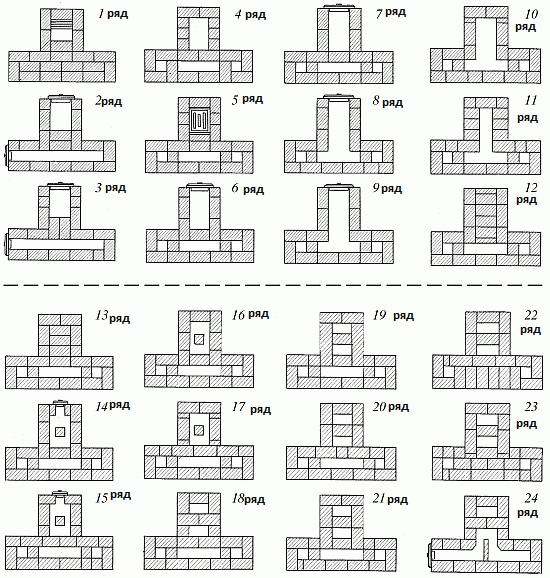
- 1st row - lay out the bottom of the ash pan. Please note that the brick that is placed behind the blower door must be hewn towards the back;
- 2nd row - install a blower door and make a channel in the rear with a cleaning door on one side;
- 3rd row - do the same as the previous one, with ligation of the seams;
- 4th row - we put cuts for lifting vertical channels in the back and increase the thickness of the walls to 18 cm;
- 5th row - laying the grate;
- Rows 6-9 - place a firebox (26 x 51 cm) in the front of the stove;
- 8-9 rows - we make a connection between the firebox and the fire chamber;
- 10th row - block the combustion door;
- Rows 11-13 - we continue to lay the fire chamber, not forgetting to make outlets to cover the firebox;
- 14th row - install a cleaning door in the front wall. To divide the front space into a chamber, the base of the chimney and connecting channels, we make a column half the size of a brick;
- 15-17 rows - do the same as the 14th, with ligation of the seams;
- Rows 18-21 - lay out the base of the cut of the upper chamber and the chimney, it should rest on the column;
- 22-23 rows - we overlap the lower heat chamber;
- 24-25 rows - we connect the upper chamber and the vertical lifting channel using a horizontal channel (the cleaning door of the horizontal channel is placed on the 24th);
- Rows 26-29 - finally installing the furnace roof (the view valve is installed on the 28th);
- 30 and to the end - lay out the chimney (pipe cross-section 13 x 25 cm).
Round stove in a metal case

This type of stove begins to give off heat soon after lighting and heats up evenly.
Dimensions - diameter 65 cm, height 229 cm. Heat output - 1.75 kW.
Materials for laying a stove with your own hands:
- ordinary clay - 0.05 cubic meters;
- sand - 0.03 cubic meters;
- brick - 260 pieces (including refractory brick - 65 pieces);
- grate (18×25 cm) - 1 pc.;
- blower door (13×14 cm) - 1 pc.;
- pre-furnace sheet (50 x 70 cm) - 1 pc.;
- fire door (21 x 25 cm) - 1 pc.;
- view latches (13 x 13 cm) - 2 pcs.;
- cleaning doors (13 x 14 cm) - 2 pcs.;
- roofing felt or roofing felt for waterproofing (diameter 85 cm) - 2 sheets;
- fireproof clay - 11 kg;
- roofing steel for the case - 6.5 sq.m.
If you set out to create a stove of this type with your own hands, then before starting to lay the stove itself, you should mark and cut holes in the steel sheets for the blower, combustion and cleaning doors, as well as for the view valves. The construction of the stove begins with the installation of the first casing drawer on a previously prepared base. Next, you need to check the verticality of the installation and fill the seams between the drawer and the base with clay mortar. Then brickwork is done inside the drawer, according to the plan shown in the drawings. One of the most important advantages of stoves in metal cases is the complete gas-tightness of the walls and quite simple internal structure. The case most often consists of only three drawers, successively mounted on each other.
List of required tools
- furnace hammer;
- pick;
- trowel;
- wash brush;
- rule;
- level;
- spirit level;
- square;
- wooden oar;
- wooden shovel;
- steel shovel;
- strukaltse.
Tools such as a sledgehammer, a whetstone, a scarpel and a rasp are used as needed. For uncoated masonry simple ovens It is enough to have a stove hammer, usually a weight, a trowel, a level, a square, etc.
Heating rectangular thick-walled stove PTO-2800.
The design of this heating stove is somewhat more complicated than PTO-2300, but its heat output is more than 2800 watts per hour versus 2300 watts, which allows it to be used for heating large room or two rooms with an area of 24 square meters. Let us recall that the heat output of 2800 watts per hour means that the stove was heated twice a day - in the morning and in the evening and gave off this amount of heat. You can increase the heat transfer of the furnace by increasing the number of fireboxes per day.
The heating rectangular thick-walled stove PTO-2800, as can be seen from the figure, has dimensions of 770 millimeters by 640 millimeters and a height of 2240 millimeters with a standard seam thickness of 5 millimeters. This seam size must be observed, since if you change it, you will increase or decrease the height of the stove, but moreover, all standard stove devices, such as, for example, the fire door, will no longer fit or will be weakened.
Now a little about the design of the heating stove and the principle of its operation. The stove is installed on the foundation, after which two layers of waterproofing from pieces of roofing felt are laid.
The furnace firebox starts from the 6th row and is designed for burning wood, but if you want to use coal as fuel, then starting from the 5th row and ending with the 19th row, you need to lay the masonry with refractory bricks and lay the firebox door, starting from the 7th row. For burning wood, you can use ordinary red ceramic brick. The quantity of bricks needed for laying a stove is indicated in the table.
So, as we have already said, this The heating rectangular thick-walled stove has a more complex design, namely, one (third) vertical channel has been added. Due to this, the movement of hot flue gases is more complex and, accordingly, the furnace heats up more strongly and its heat transfer increases. After the firebox, hot flue gases, through the heater, which is located in the side wall of the furnace, enter the first vertical channel through which they descend down to the underside, pass through it and rise through the second vertical channel up to the roof, where through the overpass they enter a small chamber, heating the walls ovens. After this, the flue gases again fall down to the underside and enter the third vertical channel, through which they pass directly into the chimney, which has a cross-section of 130 by 130 millimeters.

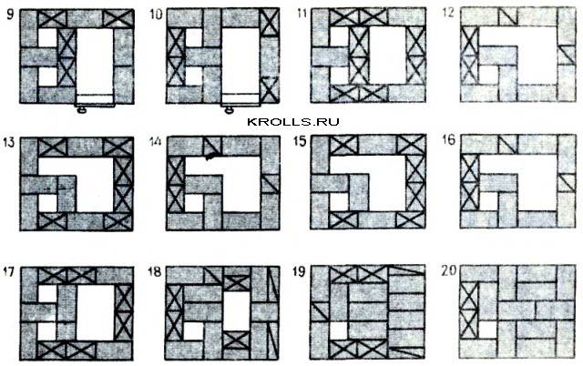

The figure below shows the order of the heating stove. All drawings of sections of the furnace A-A, B-B, B-C and D-G, which you see in the general drawing, are shown in the first drawing of the order. Remember that for proper operation the furnace must strictly observe the position of each brick, as indicated in the order drawings.
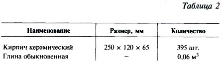
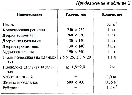
For laying the stove, ordinary red ceramic bricks are used.
You can read how to distinguish between burnt and under-heated bricks, which cannot be used in masonry, and which clay is best to use on the page Materials for the stove.
| Look on the website | |||
| Home mini steam room | Simple greenhouse | Shvedka stove | Greenhouses |
 |
 |
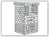 |
|