AT panel houses , built from structures designed back in the 60s, were designed foam-filled joints and cement mortar, which, however, did not ensure their tightness.
The reason for damp walls also can be:
- not completed mortar or tarred tow seams;
- insufficient thickness or large volumetric weight of backfill attic floors;
- unregulated heating system;
- high humidity of expanded clay concrete during the first years of operation building;
- insufficient wall thickness;
- replacing one building material others - with lower thermal properties;
- absence in the premises ventilation and through ventilation;
- cooling through reinforced concrete structures, not corresponding to the design thickness;
- cooling through metal beams and anchors;
- capillary penetration of moisture and floodability cellars;
- the appearance of condensate on exhaust pipes;
- wrong device vapor barrier in attic floors.
Besides, finishing layer thickness turned out to be insufficient, and the methods of its connection with the inner layer wall panels did not provide its free deformation with temperature fluctuations outside air. That's why tile exterior cladding gradually crumbled, exposing an unprotected wall from getting wet and freezing.
During operation panel buildings were discovered flow of atmospheric moisture in the places of attachment of the filling of openings due to poor sealing and incorrect installation structures of metal outer window sill coverings.
In practice operation of prefabricated buildings and buildings from expanded clay concrete blocks there are cases freezing walls in separate apartments , located mainly on the upper floors.
1.1. The walls become damp and freeze due to violations in the insulation of the attic floor.
At the points of contact attic floor to outer walls, on walls and ceilings when the outside temperature drops dampness appears.
Troubleshooting work at the joints between blocks several reduce but not completely eliminate dampness on the inner surface of the outer walls.
In apartments, located on the top floor, in the corners of rooms and at the junction of the attic floor to outer walls:
- may appear black mildew stains;
- from constant moisture wallpaper peeling off walls;
- wall surface under wallpaper getting wet.
Cause dampness and black spots on the ceiling in the corners of the house may be violation of work technology on attic floor insulation.
On attic floors expanded clay was used as a heater, the backfill thickness was 13…16 cm, instead of those required by the regulations - 25…30 cm.
Filling around the perimeter of the outer walls did not fulfill- as a result air temperature in individual rooms top floor of the house located at the ends of buildings, decreased during frost before 13…16°C.
Attic floors need to cover insulation layer from materials with insulation layer thickness specified in table 1 section of the site "Insulation of the roof and attic".
1.2. The walls become damp and freeze due to insufficient ventilation of the attic space.
Significant influence on the moisture content of the coatings during operation renders attic space ventilation. Location schemes ventilation holes attic space of buildings are shown in Fig.2.
ATTENTION! Properly performed ventilation provides drying of thermal insulation layers as from technological moisture penetrating during the construction of the building, and from moisture caused by water vapor diffusion during operation.
Errors while performing work for ventilation of coatings, are:
- device too small ventilation openings;
- lack of protection mesh ventilation holes, as a result of which the birds are unhindered make their nests there;
- device ventilation holes inclined inwards, which contributes the ingress of atmospheric moisture into the attic space;
- absence cross-ventilation of space, not providing sufficient air exchange.
ATTENTION! Properly designed and executed cover ventilation should provide about the same temperature throughout the entire surface of the roof winter period . In case of insufficient ventilation (in the case of ventilation holes along the roof overhang) during the period of negative temperatures observed temperature drop along the overhang compared with temperature of coatings in the central part of the building where it can be positive.
In the presence of snow cover on the roof it starts to melt in its central part, flowing towards the overhangs, where falls into the negative temperature zone. As a result, near overhangs ice is formed, hindering withdrawal water and melted snow and defiant education leaks in these places.
NOTE: Insufficient air movement in ventilated covers does not protect also interior space from overheating on hot summer days.
1.3. The walls become damp and freeze due to poor incorporation of balcony slabs into the walls.
Due to poor embedding in the walls balcony slabs dampness penetrates into the seams between the slab and the wall. From moisture ingress into the joint - on the wall along which the balconies are located, wet spots appear.
Dampness can spread over a large area of the wall and develop into leaks. In some rooms, traces of leaks appear on the ceilings along the rustication, wide in each direction on 12…18 cm and up to 2 m.
1.4. The walls become damp and freeze due to poor chasing of seams in the panels of the outer walls.
One of the reasons dampening and cooling of rooms in the upper floors of buildings is increased heat transfer of support nodes building structures and junctions of attic floors to the outer walls.
The error in the observance of the technology for the implementation of the nodes for supporting and adjoining attic floors to the outer walls is due to the fact that the adjoining node did not have the necessary thermal reliability.
The voids in the floor slabs were not sealed concrete plugs. Cold air acted through poorly executed caulking of the seams of the outer walls of the house into the voids of the floor slabs.
Seams between floor slabs and walls were also not sealed with mortar. BUT attic insulation layer did not meet the required standards.
Leakage and freezing, observed in panel and large-block construction, can be attributed to the failure of the design of the joints.
Based on the experience gained, some of the shortcomings in the design of the panels have been eliminated, however, as before, the problems of durability and maintainability are not always taken into account. For example, some horizontal and vertical joints use gaskets that do not last as long as the building as a whole, while at the same time their shape and location do not allow for their replacement in the future.
However, a significant role in this is played by the imperfect technology of processing and chasing the seams.
Depending on the method of air (water) protective qualities, the joints are divided into closed and open:
- in closed joints, air-protective qualities are provided by one main element;
- in open joints - two main elements, of which:
- one provides air protection,
- the other is moisture protection.
2. Sealing and sealing joints and seams in the walls.
Sealing and sealing joints and seams provide resistance joints and seams heat transfer, air, steam and moisture permeability, as well as contributes to increased strength and solidity house designs.
For joints required density and solidity apply the method mechanical injection of the mixture into the seams of structures.
quality execution of monolithic joints is achieved by observing the following technological sequence:
- wet the mating surfaces water;
- caulk seams on both sides;
- close up joints up to 2 m high with vibration seal;
- establish reinforcing cage;
- and concreted remaining part of the joint to the mark of the top of the panel.
Reinforced horizontal joints concreted simultaneously with filling vertical joint. Unreinforced part of the joint between crested exterior wall panel and floor panel also filled with concrete.
Vertical joints between the inner ribs of the wall panels necessary fill before laying floor panels.
Vertical joints between exterior wall panels and horizontal reinforced joints in the junction nodes they are monolithic after completion of installation on the gripping section with concrete grade M-100.
To prevent concrete leaks from gaps vertical joints from the inside, the gaps are caulked, a seal from the facade wooden inventory rail.
NOTE: When concreting vertical joints and adjacent reinforced knots work breaks are not allowed.
After monolithic produce sealing of external seams mastics, pastes(according to the project) and embroider the seams cement mortar.
The quality of sealing work depends:
- from surface preparation;
- dosages of mastics components;
- ensuring the design thickness of the sealing layer;
- contact width;
- continuity of sealant application;
- degree of compression of elastic gaskets;
- adhesion values of mastics.
Sealing materials, providing air and moisture tightness at the joints between the panels, must meet the requirements of the project and technical requirements sealant (Table 1.).
Table 1: Characteristics of sealing mastics for sealing joints and seams in walls.
| p/p | Mastic | a brief description of | Application | Permissible operating temperature |
| 1 | 2 | 3 | 4 | 5 |
| 1 | Sealing non-hardening building mastic (GOST 14791-79) | Viscous homogeneous mass | Closed and drained joints, as well as adjoining window and door blocks | -50°C to +70°C |
| 2 | Thiokol mastics grades U-30M and UT-31 (GOST 13489-79) | Joints of metal structural elements | -60°C to +130°C | |
| 3 | Thiokol mastics grades AM-0.5 and KB-0.5 (TU 84-246-75) | Same | Joints of external fences on an elastic basis | -50°C to +70°C |
| 4 | Thiokol mastics grades 51-UTO-40; 51-UTO-42; 51-UTO-43; 51-UTO-44; (TU 38-1054-96-72) | One-component vulcanizing mastics | For sealing joints | -40°C to +70°C |
| 5 | Organosilicon (silicone) mastic brand lastosil No. 1106 (TU 02-775-78) | Same | Same | -55°C to +90°C |
| 6 | Butyl rubber mastics brands: TsPL-2U (VTU 6-01-11-32-75); PGS (RSN 256-75) | Two-component vulcanizing mastics | Joints of external fences and junctions of window and door blocks | -40°C to +70°C |
| 7 | Germabutil-1, germabutil-2, germabutil-UM (PST Ukrainian SSR 5018-81) | The same (germabutil in the form of a two-layer tape) | Joints of external fencing and waterproofing | -50°C to +80°C |
In quality control sealing joints of building elements (panels of external walls, junctions of balcony slabs to walls, slabs of loggias, window and door frames ) need to follow for the execution of technological operations:
- preparation of starting materials for the preparation of mastic and primer;
- preparation of the working composition of mastic;
- filling ampoules with mastic;
- preparation of the working composition of the primer and adhesive mastic;
- preparation of the joint surface for applying a primer;
- primer coating;
- applying an anti-adhesive layer;
- filling joints with mastic;
- application of protective coatings on mastic sealant.
Works on sealing horizontal and vertical joints of panels should be carried out in accordance with the requirements of the project.
Joint sealing accepts the technical supervision of the customer and draws up an act surveys hidden works. Acceptance of work on sealing joints is carried out in the course of work(intermediate acceptance) and after its completion.
Acceptance of finished joint sealing documented, which is at the same time and warranty card.
3. Repair of sealing of joints and seams in external wall panels.
Repair work sealing joints and seams must precede:
- repair outer and side surfaces of wall panels;
- drying wet joints, plots walls or ceilings(from the residential premises);
- removal of damaged sealant from the repaired joint;
- removal of damaged gaskets.
ATTENTION! When repairing cleaning up the outside cavities of the repaired joint to the depth up to 50 mm. Wherein be sure to delete sealable mastics and damaged seals.
Thereafter butt establish new seals. Sealing gaskets, re-installed at the joints, must be crimped on the 20…25% diameter (width) their cross section. For this choose pads this size so that they exceed the width butt gap not less than 25% .
Sealing gaskets establish at the mouths of the joints dry, without glue. The insertion of gaskets into the joint is carried out using a rounded wooden spatula. Connect the strips along the length "on the mustache";.
Joint mouths in places where sealing mastics are applied, there should be dry and clean.
Sealing wide joints performed in two steps- first along the edges mating surfaces, and then in the middle. After installation layer of mastic by using wood paneling, soaked in soapy water , smooth and shape the surface.
In the presence of intact cement-sand base allowed application of hardening mastics film coating on top of pre-pasted compensatory layer of polymer tape width 22-40 mm. Thickness of the applied layer coverage should be 2…3 mm and come in to the surface adjacent panels not less than 30 mm.
At the ends of the panels internal walls must be limiters providing in vertical joints seam thickness at least 10 mm.
Scheme sealed joint lined exterior wall panel shown in Fig.3.

Gaps between exterior wall panels in places, compacted sealing materials should be no more than 20 mm. Coating thickness should be 2-3 mm and come in on a surface adjacent panels not less than 30 mm. Film width should be 110 mm(55 mm from the joint axis).
NOTE: Apply sealant mastics on wet surfaces, pre not primed special compounds - NOT ALLOWED.
To increase grip thiokol sealants with concrete and others building materials necessary apply primers and adhesives.
Elastic substrate under thiokol mastic sealants it is necessary made of poroizol, gernite. Glue elastic backing to working position adhesive mastics KN-2, KN-3, BK-1, BVN, isol and etc.
ATTENTION! Poor sealing of seams cannot be compensated their surface coating waterproofing and sealing compounds. Film applied on the surface of the seam, needs periodic updates due to the "aging" of the material and the loss of elasticity.
Joint repair can be performed with preliminary clearing and without clearing depending on their condition. Repair and insulation works should perform in warm time year in dry weather.
1. Repair of closed joints perform in accordance with the "Guidelines for sealing the joints of external walls" (ONTI LNII AKH, 1976) and "Recommendations for eliminating leaks and freezing in large-panel houses with closed joints" (MNIITEP, 1976).
2. Repair of open joints performed in accordance with the "Recommendations for the elimination of rain leaks and freezing in large-panel houses with open joints of the P-42/6, P-43/16 and P-30/12 series" (MNIITEP, 1980) and "Guidelines for sealing joints during repairs prefabricated residential buildings with mastic AM-0.5 and armo-sealants "BSN-13-83 (GMZhU, 1983).
4. The choice of the thickness of the outer walls, taking into account the temperature balance.
One of the reasons that the walls are damp just like is a violation of the balance of thermal protection of the walls. Those. walls are made without taking into account the temperature balance between room temperature and winter outdoor temperature.
To maintain such a balance The thickness of the outer walls must match sizes indicated in table 2.
Application solid brickwork for external walls with a thickness over 38 cm low-rise buildings from solid brick economically impractical and only allowed for raw rooms (bathroom, laundry room, sauna) with air humidity over 75%.
However, one must take into account, which is for sections of walls with increased load(walls bearing walls length 38-64 cm) and load-bearing pillars, applies only solid brick not less brand M-75.
This must be taken into account if you are just going to build your house. What if the house is already and the walls are damp?
It would be nice to find out whether the thickness of damp walls the requirements of thermal protection standards specified in table 2. And if walls are thinner than normal, then insulate the walls - clad the house outside an additional layer of brickwork or insulation for plaster on the grid, etc.
As one of the options - wall insulation indoors through additional frame installation inner wall with cladding slab insulation thick 80 mm and volumetric weight 1000 kg/m³"at a distance" (see Table 2).
Those. execute frame for fastening foam boards, glass wool and other insulation with frame cladding dry plaster.
frame fasten with insulated wall, leaving partition(thick. 50 mm) for filling it with expanded clay.
Expanded clay absorb the old moisture of the damp wall and prevent mold from spreading.
The wall thickness will increase thus by 150 mm:
- 80 mm- plates polystyrene;
- 50 mm- insulation expanded clay;
- 20 mm- thickness dry plaster.
This option is allowed for dry rooms.
Note: Later in construction industry began to produce very economical, lightweight foam blocks up to 80 mm thick. These foam blocks are convenient because do not require a frame for them and are laid on a simple cement mortar with fast-hardening additives. These plates are capable of performing the same role wall insulators inside cold rooms. That is, practically without Borders temperature balance of enclosing structures and indoor humidity.
Table 2: Choice of external wall thickness considering temperature balance.
| Material for walls | Types wall structures | Masonry thickness, mm | Weight of 1 m² of wall, kg | Resist- heat phenomenon transmission, m²*h*°С/kcal | Consumption of basic materials per 1 m² of wall | Permissible design (winter) outdoor temperature | ||
| Conditional brick, pcs. | solution, l | |||||||
| treasure- chic | thing- tourny |
|||||||
| Ordinary clay brick and silicate brick with a bulk density of 1800 kg / cm 2 | 250 | 480 | 0,57 | 102 | 62 | 25 | -3°С | |
| 380 | 710 | 0,76 | 152 | 96 | -10°С | |||
| 510 | 950 | 0,94 | 204 | 127 | -20°С | |||
| 640 | 1180 | 1,13 | 256 | 160 | -30°С | |||
| 770 | 1410 | 1,32 | 308 | 193 | -40°С | |||
| 420 | 720 | 0,93 | 152 | 85 | 50 | -20°С | ||
| 550 | 950 | 1,19 | 204 | 117 | -33°С | |||
| 680 | 1190 | 1,32 | 256 | 150 | -40°С | |||
| Walls lined from the inside with slabs 80 mm thick and with a bulk density of 1000 kg/m³ "at a distance". Laying on a "cold" solution with external and internal jointing. | 250 | 530 | 0,98 | 102 | 62 | - | -22°С | |
| 380 | 770 | 1,16 | 152 | 95 | -31°С | |||
| 510 | 1000 | 1,34 | 204 | 127 | -41°C | |||
| Efficient brick (multi-hole, with slit-like voids) with a bulk density of 1300 kg / m³ | Wall of solid masonry on a "cold" mortar with external jointing and internal plaster | 250 | 350 | 0,7 | 103 | 50 | 25 | -7°С |
| 380 | 520 | 0,96 | 154 | 76 | -21°C | |||
| 510 | 690 | 1,22 | 206 | 102 | -35°C | |||
| 640 | 860 | 1,48 | 259 | 128 | -48°C | |||
| Wall with an air gap in the masonry on a "cold" solution with external and internal plaster | 420 | 530 | 1,13 | 154 | 66 | 50 | -30°С | |
| 550 | 700 | 1,39 | 206 | 92 | -42°C | |||
| 680 | 870 | 1,65 | 259 | 118 | -55°C | |||
ATTENTION! Must be strictly followed per thickness of enclosing structures taking into account their application in given climatic conditions home building region.
5. Ways to reduce indoor humidity.
If a room with high humidity(bathroom, laundry, bath), then here dampness of the walls may be related not only with thin walls, but also with poor ventilation .
If possible, check ventilation ducts. It is possible that a foreign object has got there, which does not allow air to circulate.
Clogging check ventilation ducts can spend a very in a simple way . Enough bring a lit candle to the vent and watch the reaction of the flame, if the flame deflects towards the grid so there is traction and ventilation is not clogged. If a the candle does not react at all for proximity ventilation grill, additional devices will be required to resume air circulation.
If the channels are clean and hood is weak how the simplest option, drill at the bottom of the door leaf extra air holes into the room.
If after a while you are convinced that this does not help, then you will have to put forced exhaust in air vent bathroom.
Such fans for forced exhaust available for sale. However, you can only turn them on when indoors.(bathroom, laundry room, sauna) no one will be- and even "health can stretch along with the steam."
The bathroom is better equipped fan with humidity control. At high humidity fan will automatically delete moisture-laden air . Besides, underwear in this bathroom dries much faster.
NOTE: When abundant dampness appears, it is necessary first of all to adjust the heating system, and the air temperature in the living quarters should reach 20…22°C. And to carry out artificial drying of the walls with the obligatory intensive ventilation of the premises.
Because for interior decoration the space of rooms today, drywall is widely used, the issue of forming corners is relevant. This is especially important when building various designs from this material - arches, partitions, etc.
Our article will be devoted to the solution of this issue.
Outdoor and indoor
Walls in a room can form two types of corners:
- interior;
- outer.
They differ from each other in direction: one goes inside the room, the other - out of it. Given this, corners can be made from drywall in many ways.
Prepare Responsibly
Installation of a drywall corner, regardless of type, requires preliminary preparation. It includes:
- space cleaning;
- puttying cracks on the walls, after which we prime the walls;
 Surface primer
- carrying out the necessary calculations. Here you should calculate the length and height of the walls in the room. And, based on the fastening step, you need to calculate required amount materials;
- drawing markings on the walls, including corners.
After that, you can start installation work for assembly, as well as sheathing the frame and its corners with plasterboard sheets.
Preparing tools for work
To finish the corner with drywall, you will need the following set of tools:
- screwdriver or drill;
- drywall knife;
- metal scissors;
- set of spatulas.
You will also need the following materials:
- metal profiles (guides and rack). Instead, you can use wooden bars;
- drywall sheets;
- self-tapping screws;
- sickle;
- putty.
Such a list of materials and tools is necessary for the successful completion of the planned work.
Work with wall joints
Installation of sheets at the junction is carried out depending on the type of construction. Since there are two types of corners (external and internal), there are also two installation methods. Let's take a closer look at each specific case.
Assembling the internal structure
So, consider the installation of the inner corner. To make a structure from metal profile you need to do the following:
- install a guide profile on the floor along the surface. We fasten it to dowels;
- then it is necessary, on the other hand, to the already installed profile, to attach another profile;
- next you need to do a mirror reflection on the ceiling;
- after that, we fasten the guide profile along the entire length of the wall.
The result is an almost finished design. Next, you need to do the following operations:
 Sheeting
- along the entire length we mount rack jumpers, which are attached between the vertical guides;
- the fastening step must be done based on the load expected for the structure. The greater the load, the shorter the fastening distance will be. Use a distance of 30 to 60 cm.
This method is acceptable if one wall has already been completely sheathed with sheets. This method is very simple and therefore widely used. There is no need to suffer with cutting profiles and forming a single structure from them.
But you can use another method when you need to make cuts on the profiles and connect them with self-tapping screws. To do this, you need to do the following operations:
- we take two rack profiles and cut them so that the side of one element is attached to half of the front of the other;
 Correct connection
- we connect them with self-tapping screws;
- then we combine the entire structure with the perimeter guide.
Everything, the inner corner is ready for sheathing. Drywall in this case is attached according to the standard scheme.
Note! We first sheathe one wall with drywall, and then another, while closing the entire structure. In the second installation option, the same algorithm is observed.
Assembly of the external structure
Here main feature is the fact that there is no need to form a strong connected framework.
Mounting outer corner can be done as follows:
- we fix two rack profiles on both sides of the wall;
- after that we mount them to the perimeter profile with self-tapping screws.
 Sheet installation
Remember! That here, on the one hand, a sheet of drywall should extend to the width of the slab from the other edge.
After the sheets are fixed on both sides of the wall, you need to protect their joint with a perforated metal corner. It will protect the material from damage, which very often occurs in this particular place.
Nothing remains
When all the main operations are completed, all joints and gaps between the sheets are processed as follows:
- put a sickle on them;
- cover with putty. At the same time, we cover all the screws on top. Use a special spatula to cover the seams along the wall joint;
- rub the surface with sandpaper to a smooth surface;
- prime the surface and apply finishing material. For finishing, you can use paint, wallpaper or decorative trim.
As you can see, making a drywall corner is not difficult. Stick to the above recommendations, and you will definitely cope with all the difficulties.
Related Articles
 Preparing drywall for wallpapering
Wall panel joints
As mentioned above, the performance of large-panel houses largely depends on the design of the joints between the panels and with other elements of the building.
The joints between the panels of the outer walls must be airtight (i.e., have low air permeability and exclude the penetration of rainwater into the structure), prevent the formation of condensate at the joint (due to insufficient heat-shielding properties), and have sufficient strength to prevent the joint from appearing in it cracks.
When designing large-panel buildings, it is also necessary to take into account the features of the walls. If in brick walls loads are distributed evenly, then in large-panel ones they are concentrated at the joints of the panels. In addition, under the influence of temperature changes, the linear dimensions of the wall change. This is due to the effect of positive (on the inside) and negative (on the outside) temperature on the panel surface, as a result of which its linear dimensions change. The resulting forces lead to the formation of cracks.
According to the location of the joints, vertical and horizontal are distinguished.
Vertical joints according to the method of connecting the panels to each other, they are divided into elastically compliant and rigid (monolithic). When arranging a resilient joint (Fig. 10), the panels are connected using steel ties welded to the embedded parts of the joined elements. The wall panel of the inner transverse wall enters the groove formed by the quarters to a depth of 50 mm. The panels are connected with the help of an overlay made of strip steel, welded to the embedded parts of the panels. To seal the joint, a sealing cord of gernite on glue or poroizol on mastic is inserted into its narrow gap. From the outside, the joint is coated with a special mastic - thiokol sealant. To isolate from the penetration of moisture from the inside of the joint, they are glued to bituminous mastic a vertical strip of one layer of hydroisol or roofing material. The vertical joint well is filled with heavy concrete.
The disadvantage of elastic joints is the possibility of corrosion of steel bonds and embedded parts. Such fasteners are malleable and do not always ensure long-term joint operation of the mating panels and, therefore, cannot prevent the joint from cracking. This is because, from heating during welding, the embedded part, as it were, breaks away from the concrete into which it was embedded during manufacture. Atmospheric or condensation moisture penetrating into the gap destroys the lower surface of the embedded part.
To protect against corrosion, they are coated at the factory on all sides with zinc by spraying, hot dip galvanizing or galvanizing. After welding, during the installation of the panel, the protective layer on the front side of the embedded part and the bond-overlay is restored using gas-flame metallization. In addition, galvanized steel elements are protected by embedding them cement-sand mortar(1:1.5...1:2) at least 20 mm thick.
More reliable in operation are rigid monolithic joints. The strength of the connection between the joined elements is ensured by embedding the connecting steel reinforcement with concrete. On Fig. 11 shows a monolithic joint of single-layer wall panels with looped reinforcement outlets connected by brackets made of round steel with a diameter of 12 mm. Between the monolithic joint zone and the sealing, a vertical air cavity is formed, which serves as a drainage channel that drains water that enters the seam and releases it outside at the level of the base.

For device horizontal joints the top wall panel is laid on the bottom one cement mortar. In this case, through a horizontal seam densely filled with mortar, rainwater can penetrate mainly due to capillary suction of water through the mortar. That is why such a complex horizontal joint geometry has been adopted (Fig. 12). A so-called anti-rain barrier or a tooth in the form of a comb going from top to bottom is arranged in it. On the inclined part, the solution is interrupted and an air gap is created, within which the rise of moisture through the capillaries stops. Thus, we see that in order to ensure the normal performance of walls made of large panels for joints, various materials are used that have a wide variety of physical and mechanical properties: fixing (steel), insulating (mineral wool inserts), waterproofing (roofing material or isol), binders and sealing (concrete and mortar), sealing (poroizol or gernit and mastics). All these materials have different durability and often much less than the life of the building. That is why, when designing panel joints and their execution, it is necessary Special attention give opportunities to ensure High Quality production construction works using only materials with good physical and mechanical properties.

The connection of the panels of the internal walls of frameless buildings (Fig. 13) is carried out by welding connecting rods with a diameter of 12 mm to the embedded parts along the top of the panel. The vertical seams between the panels are filled with resilient spacers made of antiseptic soft fibreboard wrapped with roofing paper, and the vertical channel is filled with fine-grained concrete or mortar.

On Fig. 14 shows the assembly of floor slabs resting on the inner panel and the connection of the panels with the help of a self-locking bolt.

Often, the horizontal joint between the bearing panels of the transverse walls and ceilings is designed as a platform type (Fig. 15), a feature of which is the support of the ceilings on half the thickness of the transverse wall panels, in which the forces in the upper wall panel are transferred to the lower one through the supporting parts of the floor panels.

The seams between the panels and slabs are made on the mortar. However, in case of incomplete filling of the joints with mortar in some areas of the panels, there may be a danger of stress concentration. To prevent this phenomenon, a cement-sand plasticized paste is used for butt joints, from which thin seams 4–5 mm thick can be obtained. Such a paste consists of Portland cement grade 400...500 and fine sand with a maximum particle size of 0.6 mm (composition 1:1) with the addition of a plasticizing and antifreeze additive sodium nitrate in an amount of 5...10% by weight of cement. Such a paste, as it were, glues the panels together.
In the construction of large-panel buildings, there are many other joint designs, however, the requirements for them and the principles of execution are common.
Frame-panel buildings and their structures
In the construction of public and partially residential buildings, frame structural schemes are widely used. A frame-panel building is a building with bearing base from a prefabricated reinforced concrete frame with hinged or floor-supported walls. Grid of columns 6*3, 6*6, 7.2*7.2. Floor height depending on functional purpose building and its premises.
Advantages:
Separate functions of load-bearing and enclosing structures
Reducing the consumption of concrete and the mass of the building by approximately 2 times
A wide variety of space-planning solutions with the possibility of implementing a flexible layout
Good conditions for modernization and redevelopment
Possibility of solving external walls in different options
There are frame systems, frame-bonded and bonded.
frame system(Fig. 16) consists of columns, rigidly connected to them by beams of floors, located in mutually perpendicular directions and thus forming a rigid structural system. The connections of columns and crossbars are complex and very laborious, requiring a significant consumption of metal. The columns of buildings with a frame system have a variable section along the height of the building. If the frame is made in a monolithic version, then it is more rigid than prefabricated, but at the same time more laborious. This system has limited application in the construction of multi-storey civil buildings.

In frame-braced systems(Fig. 12.19) the joint work of the frame elements is achieved by redistributing the share of participation in it of frames and vertical walls-links (diaphragms). The diaphragm walls are located along the entire height of the building, rigidly fixed in the foundation and with adjacent columns. They are placed in a direction perpendicular to the direction of the frames, and in their plane. The distance between the tie walls is usually 24 ... 30 m. They are flat and spatial. Cross-links-diaphragms are arranged through the entire width of the building. In terms of the degree of provision of spatial rigidity, metal consumption and labor intensity, frame-bonded frames occupy an intermediate position between frame and bonded ones. These systems are used in the design public buildings up to 12 floors high with unified structural and planning grids 6x6 and 6x3 m.

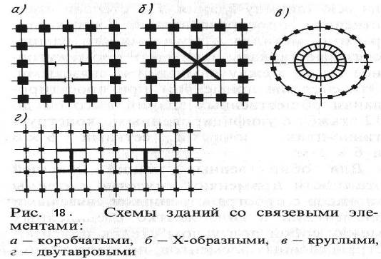
For public buildings with higher storeys, apply communication systems frames with spatial connecting elements in the form of walls rigidly connected to each other at an angle or spatial elements passing along the entire height of the building, forming the so-called "stiffening core" (Fig. 18). These spatial bonded stiffeners are fixed in the foundations and connected to the ceilings, forming floor-by-floor horizontal connections - diaphragms (disks), which perceive the horizontal (wind) loads transferred to the walls. Consumption of steel and concrete in buildings with bracing systems is 20...30% less compared to frame and frame-braced ones.
Spatial connection elements are usually placed in the central part
The rigidity of the building is ensured by: the creation of a horizontal disk with the help of floor slabs. Wall panels in this case are self-supporting or hinged.
The spatial rigidity of high-rise frame buildings is also ensured by the creation of special hard horizontal disks that form the so-called technical floors. They are also used for the location of engineering equipment. Such spatial horizontal disks, together with vertical ones, provide good rigidity of buildings. In the practice of building buildings with 60 ... 100 floors, bracing systems are used in the form of lattice braced or braced trusses, rigidly fastened at the corners and forming, as it were, an outer box-shell in which the building is enclosed. This is very efficient system, as it has high spatial rigidity and, together with the internal stiffening core, perceives horizontal loads.
To reduce the total mass of structures of frame high-rise buildings, lightweight concrete is used, which makes it possible to reduce the mass of the above-ground part of the building by almost 30%. External walls are usually used hinged lightweight type.
Crossbars can be located in the longitudinal and transverse directions.
Precast concrete frame elements (Figure 20) include columns rectangular section you are one or two floors with one console for the outer row and two consoles for the middle row; crossbars of tee section with one or two shelves for supporting floor slabs and flights of stairs; floor slabs (multi-hollow or solid), consisting of inter-column, wall slabs with grooves for columns and rows) 1200, 1500 mm wide.

The conjugation of the frame elements carried out by the support is called a node. The node includes:
column joint (Fig. 21, a, b). The column is supported through the concrete protrusions of the heads, welding the reinforcement outlets and monolithic the joint;
support of the crossbar on the console of the column (Fig. 21, c) On the surface, the console is fixed by welding embedded parts, at the top - with a steel plate welded to the embedded parts of the column and crossbar, then the seams are sealed with mortar;
support of the floor slab on the crossbar (Fig. 21, d). The stacked plates on the shelves of the crossbars are interconnected by steel ties, the gaps between them are sealed with mortar.
Today, traditional and innovative cladding materials and solutions are used to form the joint between the ceiling and the wall. Of course, the most common solutions to this problem are the plinth and stucco.
Ceiling plinth
In some residential buildings built during the Soviet era, the joint was not formalized in any way - it was simply rounded. In those years, such a design of the premises was understandable - it was necessary to build cheaply and quickly.
The issue of decorating the joint today is different, because almost all decorative solutions are cheaper and easier than fussing with rounding.
Choosing a ceiling plinth
So:
- The main criterion for choosing a ceiling plinth is indoors. This determines the width of the profile.
In other words: the lower the room, the narrower the plinth should be and, accordingly, vice versa; - The second question is the material from which the decorative plinth is made. Ceiling skirting boards can be made of gypsum, polyurethane, wood, foam.
You need to choose the material not only in accordance with your personal preferences, but also based on the technical parameters of the ceiling and walls.
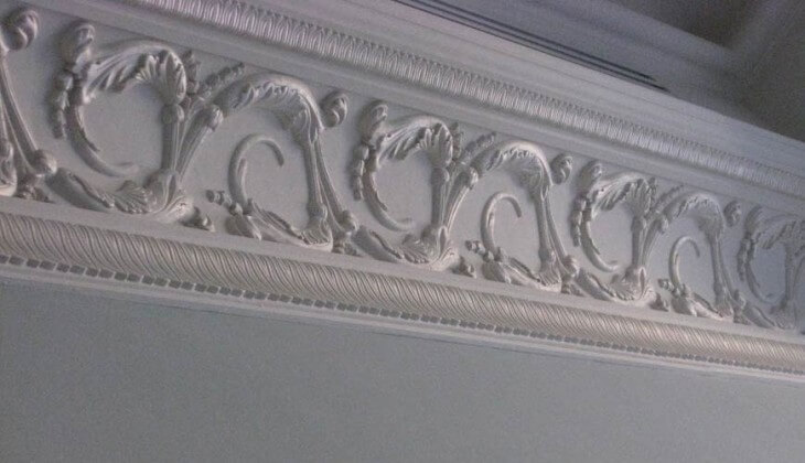
If you want to make curly molding, then the conversation should be carried out only on a plaster plinth, and about no other. Such skirting boards have been used for decoration since ancient times, and they are still very much in demand in modern designs.
Finishing the joint between the wall and the ceiling with a wooden plinth, you need to take into account the fact that other finishing materials must also be wooden.
Skirting board installation
So:
- it is necessary from the corner of the room, for which the profile is cut at a right angle on one side and at an angle of 45 degrees on the other. For this, a joiner's miter box is used, which provides for the presence of stencils for angles of 90, 67.5, 67, 45 degrees;
- Ceiling skirting boards are glued either to putty or to special polymer glue (“Bustilat” or polymer PVA, or based on polymer liquid hardeners such as “liquid nails” and epoxy resin).
In addition, the instructions of many manufacturers provide for the use of "Moment", "Dragon" or white (transparent) silicone.
Advice! To mount wooden plinth on the ceiling, in addition to the adhesive composition, yellow self-tapping screws are used. In addition, screws will be required when installing a wide gypsum plinth, when the putty cannot withstand the mass of the profile and additional support is required until the composition hardens.
To dock ceiling plinth in the span of the wall, an oblique cut is used. This approach allows you to make the connection almost invisible.
If the plinth (see) is textured, then you need to make sure that the pattern converges on the profiles. For gypsum products, profiles are joined at a right angle, and visible gaps must be sealed with a putty solution.
Begin:
- First of all, skirting boards are installed on the prepared joint of the ceiling and walls in different direction: initially one corner of the room is made, from which installation is already carried out around the perimeter of the entire room;
- If the plinth is fixed to the putty, then the mortar should completely fill the space between the plinth and the junction of the wall and ceiling. If the plinth is attached to the adhesive, then only those parts of the profile that will be adjacent to the main surface should be smeared with it (depending on the materials of the wall and ceiling);
- When installing the last profile on the perimeter or in the span, the plinth is cut 1 mm larger than required. When the plinth is installed in its place, it will make the joint between adjacent plinths absolutely invisible;
- The gaps that remain after installation must be sealed with putty so that the profile looks like a single whole. If the plinths are wooden, then wood putty is used.
In addition, you can use thin plates that are cut from the profile itself.
Maybe with a small brush. If you want to highlight relief images, then you need to use artistic brushes.
This is a rather painstaking work, not always done by hand.
It should be noted: far from every room, the inner or outer corners correspond to the stencil of the miter box, so the marking of the plinth is sometimes done manually:
- The profile must be attached to the junction.
- before turning, a line is drawn along the ceiling.
- The same is done on the other side.
- If you attach a plinth, then on the ceiling it will be crossed by a line running at an angle.
- The point of intersection and the point of the lower extreme corner are the reference point for the cut line. The cut is made in the direction of the wrong corner of the profile.
Installation of molded cornices
Advice! The first step is to prepare the surface of the wall. To do this, we apply the cornice to the corner and make marks at the place where the profile fits on the wall and ceiling.
About the correct marking and preparation of the ceiling for stucco cornices, you can see photos and videos on the Internet.
Using a lace-beat, we beat off the lines along the perimeter of the room, taking the corner marks as a basis. It is necessary to perforate the ceiling and walls with a drill to ensure a better grasp of the elements.
So:
- starts from the corners. To do this, we cut the profile on one side at an angle of 45 degrees.
The second end of the profile must be cut using a miter box for more accurate cutting; - After this, cycles inside notches are applied to the cornice;
- We prepare a plaster solution, add a small amount of PVA to the mixture;
- Distribute evenly adhesive solution along the eaves;
- We attach the cornice to the wall at the attachment point, move it a little to the right and left to squeeze out the excess mortar and ensure good adhesion;
- If the stucco is light and small, then it may well hold on to the mortar itself. For large stucco, special fasteners are required;
- Heavy stucco is fixed on galvanized screws and dowels;
- The eaves must be held at the attachment point until the moment of complete setting (several minutes);
- The remains of the solution are removed with a spatula or cycles. Finally, you can walk along the entire eaves with a brush dipped in water to remove excess mortar.
To seal the attachment points, gaps and crevices, use a gypsum mortar.
If the installation of the stucco cornice was carried out incorrectly or there are difficulties with aligning the profiles, then the problem area must be removed as soon as possible. The wall section is cleaned again before the mortar has time to harden.
Complete drying will occur 2-3 days after the installation of the eaves. Uneven areas can be sanded using sandpaper.
After sanding, the cornice is coated with a primer, painted with white paint so that the material can retain its color for a long time.
When the renovation of a room comes to an end, reasonable questions arise: What is the best way to make an angle between the wall and the ceiling? How can you hide defects or technical seams between the wall and the ceiling? How to make color selection? Let's talk about everything in order.
Pairing walls and ceiling is important
First of all, first of all ... partitions, and then, the ceiling!
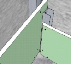
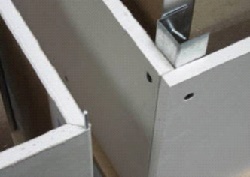
For the first time, the builder faces the issue of joining the ceiling at the stage of erecting partitions. The upper junction causes stress for many.
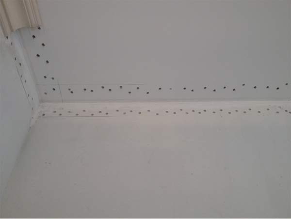
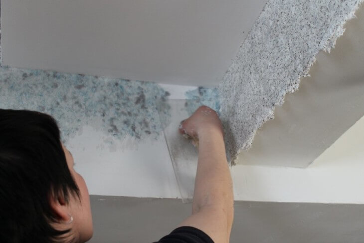
In the case of a block wall, it is common to first smear the top edge of the block or brick with glue, and then “press” it between the wall and the ceiling. As a result, the adhesive or solution partially remains on the block, partially squeezed out. A gap is formed, which must be managed to putty. And even if the putty was successful, a gap may still appear. The best, in my opinion, is to use polyurethane foam. You can use it when the partition has gained the necessary strength.

Using foam to fill gaps
First, we insert a gun with a foam bottle into the upper seam and carefully pass from the outer and outer sides of the partition. After the foam dries, we remove the excess with an ordinary construction knife. Ready! The result is a high-tech, durable junction. This pairing perfectly compensates for the movement of the ceiling and walls and provides excellent sound insulation to the room.
In case of plasterboard partitions trying to close the gap with putty. When installing drywall sheets, try to first leave a gap of no more than 5 millimeters at the top. And then seal the seam with acrylic sealant. Sealant, like foam, compensates for small deformations.
Perfect angle or bummer?
Don't be scared, it's all right! A bummer in architecture is called decorative element different in its cross section.
Many have heard these terms:
- Cornice;
- Ceiling plinth;
- Baguette;
- Border.

Ceiling plinth
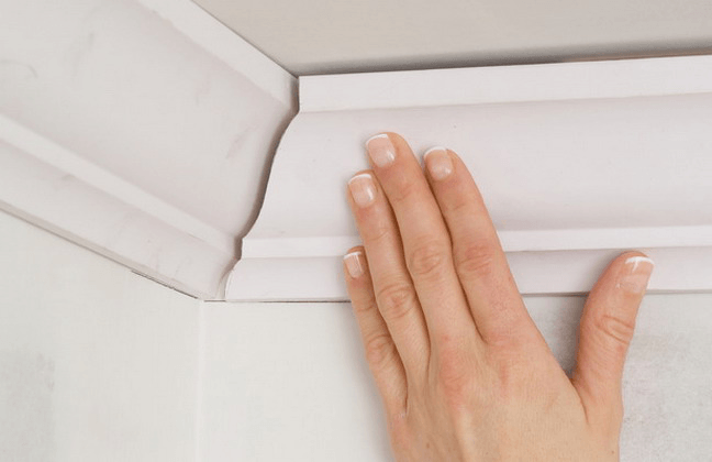
However, professional builders usually call this element a fillet (it is also a bar that covers the joint between the wall and the ceiling).
There are many materials from which this decorative element is made. It can be classic plaster moldings (there are workshops that still make them by hand), and wood, and modern plastic fillets, and even luxurious marble.
When choosing, it is important to remember that the width of the cornice affects the perception of the room by people. A wide element will visually reduce the height of the ceiling and the volume of the room. While narrow, on the contrary, increases the height of the ceiling and the volume of the room. And the choice of color should be done carefully - too contrasting color will “pull out” the cornice from the interior.
Depending on the material, the installation methods also differ. If plastic parts are glued, then wood, plaster moldings and others are more heavy materials fastened with nails or screws.

Fillet on the ceiling
We fix modern "stucco molding"
Let's focus on fastening polyurethane fillets, as this is the most affordable and common material today.
First, we calculate the materials, and prepare the tool.
We consider the length of all the walls of the room and divide by the length of one plank. The number obtained as a result of the calculation is rounded up to the nearest integer. It is recommended to buy fillets with a small margin. Glue "liquid nails" or acrylic sealant is perfect as a fastener. By the way, acrylic sealant will also be needed to fill the seams between the baseboard, wall and ceiling.

Acrylic sealant
Required tool:
- Circular saw for cutting corners. Although, an ordinary hacksaw for metal is quite suitable.
- Template, he is a miter box for sawing an angle of 30.45 degrees.
- Construction knife.
Closing ceiling gaps
It is most convenient to start installing slats with internal corners moving along straight lines. Next, install the plinth in the miter box. We press the smooth surface against the side wall and cut it down at an angle of 45 degrees for right angles. If the angle of joining the walls is different, the sawing angle is determined experimentally. Attention! For one corner or slope, the planks must be mirror sawn. After the stucco is ready, we begin to glue. To do this, apply glue to the side surfaces of the fillet and gently press from the corner along the entire length. We continue to glue the planks end-to-end.

We continue to glue the planks end-to-end
Important! If you can't get a perfect fit, you can use a thin steel wire as connecting pins.
After all the strips are glued, we seal the seams between the ceiling, baseboard and wall with a thin layer of acrylic sealant. We remove the excess with a napkin or a “universal tool”, i.e. finger. Stucco has transformed your ceiling!
Stucco has transformed your ceiling
If you still find it difficult to decide on the choice of stucco, calculate its quantity or choose the color of the ceiling and walls, do not be discouraged. Many manufacturers' websites have free online services for selecting materials, calculating their quantity, as well as selecting the color of the ceiling and walls. It all works very simply. You enter the online service. Specify the dimensions of your room, make a color selection, if necessary, and determine the number of decorative elements.
Be bolder, experiment with colors and materials, and your home will be filled with beauty and comfort!