Description of a simple and reliable thermostat circuit for a heating system.
Russian winter is harsh and cold, and everyone knows it. Therefore, rooms where people are located must be heated. The most common is central heating or individual gas boilers.
Situations often arise when neither one nor the other is available: for example, in open field there is a small room pumping station water supply, and there is a driver on duty around the clock. It could also be a guard tower or a separate room in a large uninhabited building. You can find many such examples.
In all these cases, it is necessary to arrange heating using electricity. If the room is small, then you can get by with regular oil electric radiator household use. For a larger room with an area of about 15 - 20 square meters Most often, heating is done with water using a radiator welded from pipes, which is often called a register.
If you leave things to chance and do not monitor the temperature of the water, then sooner or later it will simply boil and the matter may end in the failure of everything, especially it heating element. To prevent such an unfortunate incident from happening, the heating temperature is controlled by a thermostat.
One of possible options similar device and is proposed in this article. Of course, this winter is already coming to an end, but we should not forget that it is best to prepare a sleigh in the summer.
Functionally, the device can be divided into several nodes: the temperature sensor itself, and the load control device. What follows is a description of the individual parts, their diagram and operating principle.
Temperature sensor
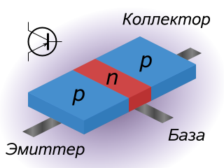
A distinctive feature of the described design is that a conventional bipolar transistor, which allows you to abandon the search and purchase of various types of sensors, such as TCM.
The operation of such a sensor is based on the fact that, like all semiconductor devices, the parameters of transistors depend to a large extent on temperature environment. First of all, this is the reverse collector current, which increases with increasing temperature, which negatively affects the operation, for example, of amplifier stages. Their operating point shifts so much that significant signal distortion occurs, and subsequently the transistor simply stops responding to the input signal.
This situation is inherent mainly in circuits with a fixed base current. Therefore, circuits of transistor stages with elements are used feedback, which stabilize the operation of the cascade as a whole, and also reduce the effect of temperature on the operation of the transistor.
This temperature dependence is observed not only in transistors, but also in diodes. To verify this, it is enough to “ring” any diode in the forward direction using a digital multimeter. As a rule, the device will show a figure close to 700. This is exactly the forward voltage drop across the open diode, which the device shows in millivolts. For silicon diodes at a temperature of 25 degrees Celsius, this parameter is approximately 700 mV, and for germanium diodes about 300.
If you now warm up this diode a little, at least with a soldering iron, then this figure will gradually decrease, so it is believed that the temperature coefficient of voltage for diodes is -2 mV/deg. The minus sign in this case indicates that with increasing temperature forward voltage on the diode will decrease.
This dependence also allows diodes to be used as temperature sensors. If you use the same device to “ring” the transitions of the transistor, the results will be very similar, which is why transistors are quite often used as temperature sensors.
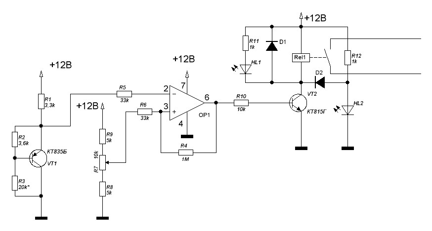
In our case, the operation of the entire thermostat is precisely based on this “negative” property of the cascade with a fixed base current. The thermostat circuit is shown in Figure 1.
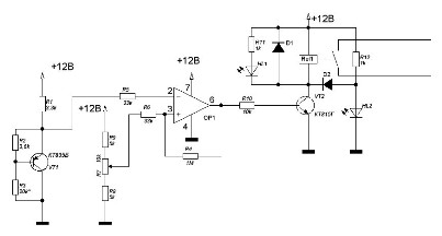
Figure 1. Thermostat diagram (clicking on the picture will open the diagram on a larger scale).
The temperature sensor is assembled on a VT1 transistor, type KT835B. The load of this stage is resistor R1, and resistors R2, R3 set. The fixed bias, which was mentioned just above, is set by resistor R3 so that the voltage at the emitter of the transistor at room temperature is about 6.8 V. Therefore, in the diagram there is an asterisk (*) in the designation of this resistor. There is no need to achieve special accuracy here, as long as this voltage is not much less or more. Measurements should be carried out relative to the collector of the transistor, which is connected to the common wire of the power source.
Transistor p-n-p structures KT835B was not chosen by chance: its collector is connected to a metal body plate, which has a hole for attaching the transistor to the radiator. For this hole the transistor is attached to a small metal plate, to which the supply wire is also attached.
The resulting sensor is attached using metal clamps to the heating system pipe. Since, as already noted, the collector is connected to the common wire of the power source, there is no need to install an insulating gasket between the pipe and the sensor, which simplifies the design and improves thermal contact.
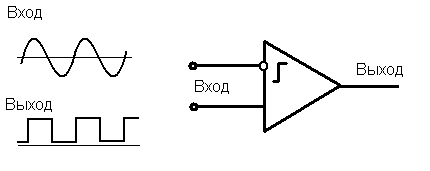
Comparator
To set the temperature, a comparator is used, made on an operational amplifier OP1 type K140UD608. Through resistor R5, voltage from the emitter of transistor VT1 is supplied to its inverting input, and voltage from the motor of variable resistor R7 is supplied to the non-inverting input through resistor R6.
This voltage sets the temperature at which the load will turn off. Resistors R8, R9 set the upper and lower range of the comparator response threshold, and therefore the temperature control limits. Using resistor R4, the necessary hysteresis of the comparator operation is ensured.
Load control device
The load control device is made of transistor VT2 and relay Rel1. There is also an indication of the operating modes of the thermostat. These are LEDs HL1 red, and HL2 green. Red means heating and green means the set temperature has been reached. Diode VD1, connected in parallel with the winding of relay Rel1, protects transistor VT2 from self-induction voltages arising on the coil of relay Rel1 at the moment of shutdown.
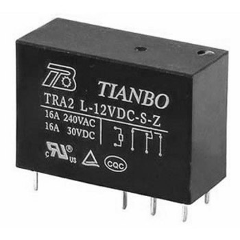
Modern small-sized relays allow switching fairly large currents. An example of such a relay is the Tianbo relay shown in Figure 2.
Figure 2. Small-sized relay from Tianbo.
As can be seen in the figure, the relay allows current switching up to 16A, which allows you to control a load with a power of up to 3KW. This is the maximum load. To somewhat facilitate the operating mode of the contact group, the load power should be limited to 2...2.5 kW. Such relays are currently used very widely in automotive and household appliances, for example, in washing machines. At the same time, the dimensions of the relay do not exceed the size of a matchbox!
Operation and adjustment of the thermostat
As was said at the beginning of the article, at room temperature the voltage at the emitter of transistor VT1 is about 6.8 V, and when heated to 90°C, the voltage drops to 5.99 V. To conduct such experiments, a table lamp with a metal lampshade is suitable as a heater. and for measuring temperature, a Chinese digital multimeter with a thermocouple, for example DT838. If the sensor of the assembled device is mounted on a lampshade, and the lamp is turned on through a relay contact, then it will be possible to check the operation of the assembled circuit using such an installation.
The operation of the comparator is designed in such a way that if the voltage at the inverting input (temperature sensor voltage) is higher than the voltage at the non-inverting input (temperature setpoint voltage), the voltage at the comparator output is close to the voltage of the power source, in this case it can be called a logical unit. Therefore, the transistor switch VT2 is open, the relay is turned on, and the relay contacts turn on the heating element.
As it warms up heating system Temperature sensor VT1 also heats up. The voltage on its emitter decreases with increasing temperature, and when it becomes equal, or rather slightly less, than the voltage set on the motor of the variable resistor R7, the comparator goes into a logical zero state, so the transistor is turned off and the relay is turned off.
The heating element is de-energized and the radiator begins to cool. Transistor sensor VT1 also cools down, and the voltage at its emitter rises. As soon as this voltage becomes higher than that set by resistor R7, the comparator will go into state high level, the relay will turn on and the process will repeat again.
A little about the operation of the display circuit, or more precisely about the purpose of its elements. The red LED HL1 turns on together with the relay winding Rel1, and indicates that the heating system is heating. At this time, transistor VT2 is open, and LED HL2 is shunted through diode D2, the green light is off.
When the set temperature is reached, the transistor will close and turn off the relay, and with it the red LED HL1. At the same time, the closed transistor will stop shunting the HL2 LED, which will light up. Diode D2 is necessary so that the HL1 LED, and with it the relay, cannot turn on through the HL2 LED. Any LEDs will do, so their type is not specified. Widespread imported diodes 1N4007 or domestic KD105B are quite suitable as diodes D1, D2.
Thermostat power supply
The power consumption of the circuit is small, so any power supply can be used. network adapter made in China, or assemble a stabilized 12V rectifier. The current consumption of the circuit is no more than 200mA, so any transformer with a power of no more than 5W and an output voltage of 15...17V is suitable.
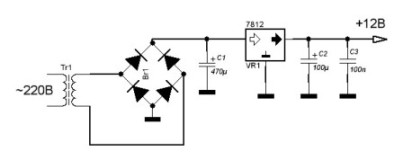
The power supply circuit is shown in Figure 3. The diode bridge is also made using 1N4007 diodes, and the +12V voltage stabilizer is based on an integrated stabilizer type 7812. The power consumption is low, so there is no need to install the stabilizer on the radiator.
Figure 3. Thermostat power supply.
The design of the thermostat is arbitrary, most of the parts are mounted on printed circuit board, it is better if the power supply is mounted there too. The transistor sensor is connected using a shielded two-core cable, while the collector of the transistor is connected through the shield.
It is desirable that there is a three-pin connector at the end of the cable, and a mating part on the board. You can also install a small-sized terminal block, although this is less convenient than the connector. This connection will greatly facilitate the installation of the sensor and the entire device at the site of application.
The finished device should be placed in a plastic case, and a temperature setting resistor R7 and LEDs HL1 and HL2 should be installed outside. It is better if these parts are also soldered on the board, and holes are made for them in the case.
Connection to the power network and connection of the heater is carried out through a terminal block, which should be secured inside the plastic case. To protect the entire device as a whole, the connection should be made in accordance with the PUE, using protection equipment.
Several similar thermostats were manufactured and they all showed acceptable temperature control accuracy, as well as very high reliability, because with such a simple circuit, there is actually nothing to break.
The operation of a gas or electric boiler can be optimized by using external control of the unit. Commercially available remote thermostats are designed for this purpose. This article will help you understand what these devices are and understand their varieties. It will also discuss the question of how to assemble a thermal relay with your own hands.
Purpose of thermostats
Any electric or gas boiler is equipped with an automation kit that monitors the heating of the coolant at the outlet of the unit and turns off the main burner when the set temperature is reached. Equipped with similar means and solid fuel boilers. They allow you to maintain the water temperature within certain limits, but nothing more.
In this case, the climatic conditions indoors or outdoors are not taken into account. This is not very convenient; the homeowner has to constantly select the appropriate operating mode for the boiler on his own. The weather can change during the day, then the rooms become hot or cool. It would be much more convenient if the boiler automation was oriented towards the air temperature in the premises.
To control the operation of boilers depending on the actual temperature, various heating thermostats are used. Being connected to the boiler electronics, such a relay turns off and starts heating, maintaining the required temperature of the air, not the coolant.
Types of thermal relays
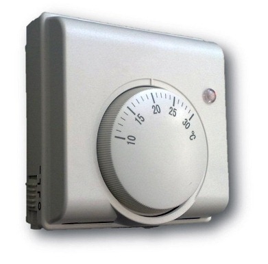
A conventional thermostat is a small electronic unit installed on the wall in a suitable location and connected to a heat source by wires. There is only a temperature regulator on the front panel; this is the cheapest type of device.
In addition to it, there are other types of thermal relays:
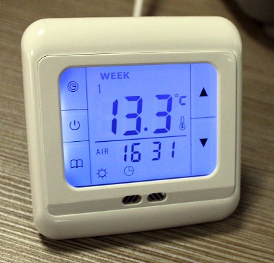
- programmable: have a liquid crystal display, connect via wires, or use wireless communication with a boiler. The program allows you to set temperature changes at certain times of the day and by day during the week;
- the same device, only equipped with a GSM module;
- autonomous regulator powered by its own battery;
- wireless thermostat with a remote sensor to control the heating process depending on the ambient temperature.
Note. A model where the sensor is located outside the building provides weather-dependent control of the operation of the boiler installation. The method is considered the most effective, since the heat source responds to changing weather conditions even before they affect the temperature inside the building.
Multifunctional thermal relays that can be programmed significantly save energy. During those hours of the day when no one is home, support high temperature the rooms don't make sense. Knowing his family's work schedule, the homeowner can always program the temperature switch so that at certain times the air temperature drops and the heating turns on an hour before people arrive.
Household thermostats equipped with a GSM module are capable of providing remote control of the boiler installation via cellular communication. Budget option– sending notifications and commands in the form of SMS messages with mobile phone. Advanced versions of devices have their own applications installed on a smartphone.
How to assemble a thermal relay yourself?
Heating control devices available for sale are quite reliable and do not cause any complaints. But at the same time, they cost money, and this does not suit those homeowners who have at least a little knowledge of electrical engineering or electronics. After all, understanding how such a thermal relay should function, you can assemble and connect it to the heat generator with your own hands.
Of course, not everyone can make a complex programmable device. In addition, to assemble such a model, it is necessary to purchase components, the same microcontroller, digital display and other parts. If you are new to this matter and have a superficial understanding of the issue, then you should start with some simple circuit, assemble it and put it into operation. Having achieved a positive result, you can move on to something more serious.
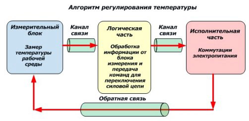
First, you need to have an idea of what elements a thermostat with temperature control should consist of. The answer to the question is given circuit diagram, presented above and reflecting the algorithm of the device. According to the diagram, any thermostat must have an element that measures temperature and sends an electrical impulse to the processing unit. The latter’s task is to amplify or convert this signal in such a way that it serves as a command to the actuator - the relay. Next we will present 2 simple circuits and we will explain their work in accordance with this algorithm, without resorting to specific terms.
Circuit with zener diode
A zener diode is the same semiconductor diode that passes current only in one direction. The difference from a diode is that the zener diode has a control contact. As long as the set voltage is supplied to it, the element is open and current flows through the circuit. When its value falls below the limit, the chain breaks. The first option is a thermal relay circuit, where the zener diode plays the role of a logical control unit:
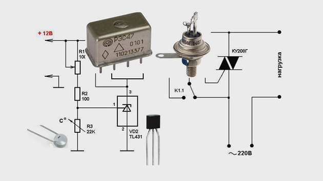
As you can see, the diagram is divided into two parts. On the left side is the part preceding the relay control contacts (designation K1). Here measuring unit is a thermal resistor (R4), its resistance decreases with increasing ambient temperature. The manual temperature controller is a variable resistor R1, the power supply to the circuit is 12 V. In normal mode, a voltage of more than 2.5 V is present at the control contact of the zener diode, the circuit is closed, the relay is turned on.
Advice. Any inexpensive commercially available device can serve as a 12 V power supply. Relay – reed switch brand RES55A or RES47, thermal resistor – KMT, MMT or similar.
As soon as the temperature rises above the set limit, the resistance of R4 will drop, the voltage will become less than 2.5 V, and the zener diode will break the circuit. Then the relay will do the same, turning off the power part, whose diagram is shown on the right. Here, a simple thermal relay for the boiler is equipped with a triac D2, which, together with the closing contacts of the relay, serves as an executive unit. The boiler supply voltage of 220 V passes through it.
Circuit with logic chip
This circuit differs from the previous one in that instead of a zener diode, it uses a K561LA7 logic chip. The temperature sensor is still a thermistor (designation VDR1), only now the decision to close the circuit is made by the logical block of the microcircuit. By the way, the K561LA7 brand has been produced since Soviet times and costs mere pennies.
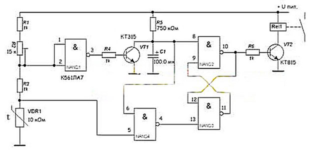
For intermediate amplification of pulses, the KT315 transistor is used; for the same purpose, a second transistor, KT815, is installed in the final stage. This diagram corresponds to the left side of the previous one; the power unit is not shown here. As you might guess, it may be similar - with the KU208G triac. The operation of such a homemade thermal relay has been tested for ARISTON boilers, BAXI, Don.
Conclusion
Connecting a thermostat to the boiler yourself is not a difficult task; there is a lot of material on this topic on the Internet. But making it yourself from scratch is not so easy; in addition, you need a voltage and current meter to make the settings. Buy finished product or take on making it yourself - the decision is up to you.
Autonomous heating of a private house allows you to choose individual temperature conditions, which is very comfortable and economical for residents. In order not to set a different mode indoors every time the weather changes outside, you can use a thermostat or thermostat for heating, which can be installed on both radiators and the boiler.
Automatic room heat regulation
What is this for?

- The most common in the area Russian Federation is , on gas boilers. But such, so to speak, luxury is not available in all areas and localities. The reasons for this are the most banal - the lack of thermal power plants or central boiler houses, as well as gas pipelines nearby.
- Have you ever visited a residential building, pumping station or weather station in a remote area from densely populated areas? winter time when the only means of communication is a diesel-powered sled? In such situations, very often they arrange heating with their own hands using electricity.
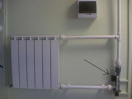
- For small spaces, for example, one room for the person on duty at a pumping station, it is enough - it will be enough for the harshest winter, but for a larger area a heating boiler and a radiator system will be required. To maintain the desired temperature in the boiler, we bring to your attention a homemade control device.
Temperature sensor
- This design does not require thermistors or various sensors type TSM, here an ordinary bipolar transistor is used instead. Like all semiconductor devices, its operation largely depends on the environment, more precisely, on its temperature. As the temperature rises, the collector current increases, and this negatively affects the operation of the amplifier stage - the operating point shifts until the signal is distorted and the transistor simply does not respond to the input signal, that is, it stops working.
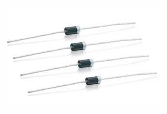
- Diodes are also semiconductors, and rising temperatures negatively affect them too. At t25⁰C, the “continuity” of a free silicon diode will show 700 mV, and for a permanent one - about 300 mV, but if the temperature rises, the forward voltage of the device will decrease accordingly. So, when the temperature increases by 1⁰C, the voltage will decrease by 2mV, that is, -2mV/1⁰C.
- This dependence of semiconductor devices allows them to be used as temperature sensors. The entire operation circuit of the thermostat is based on this negative cascade property with a fixed base current (diagram in the photo above).
- The temperature sensor is mounted on a transistor VT1 type KT835B, the cascade load is resistor R1, and the operating mode is DC The transistor is set by resistors R2 and R3. To ensure that the voltage at the transistor emitter at room temperature is 6.8V, a fixed bias is set by resistor R3.
Advice. For this reason, in the diagram R 3 is marked with * and special accuracy should not be achieved here, as long as there are no large differences. These measurements can be made relative to a transistor collector connected by a power source to a common drive.
- Transistor pnp KT835B specially selected, its collector is connected to a metal body plate that has a hole for attaching the semiconductor to the radiator. It is through this hole that the device is attached to the plate, to which the underwater wire is also attached.
- The assembled sensor is attached to the heating pipe using metal clamps, and the structure does not need to be insulated with any gasket from the heating pipe. The fact is that the collector is connected by one wire to the power source - this greatly simplifies the entire sensor and makes contact better.
Comparator
- Comparator, mounted on an operational amplifier OR1 type K140UD608, sets the temperature. The invertible input R5 is supplied with voltage from the emitter VT1, and through R6 the non-invertible input is supplied with voltage from the engine R7.
- This voltage determines the temperature for switching off the load. The upper and lower ranges for setting the threshold for triggering the comparator are set using R8 and R9. The required posteresis of the comparator is provided by R4.
Load management
- On VT2 and Rel1 a load control device has been made and the thermostat operating mode indicator is located here - red when heating, and green when the required temperature has been reached. A diode VD1 is connected in parallel to the Rel1 winding to protect VT2 from voltage caused by self-induction on the Rel1 coil when turned off.
Advice. The figure above shows that the permissible switching current of the relay is 16A, which means it allows control of a load of up to 3 kW. Use a device with a power of 2-2.5 kW to lighten the load.
power unit
- An arbitrary instruction allows for a real thermostat, due to its low power, to use a cheap Chinese adapter as a power supply. You can also assemble a 12V rectifier yourself, with a circuit current consumption of no more than 200mA. For this purpose, a transformer with a power of up to 5 W and an output of 15 to 17 V is suitable.
- The diode bridge is made using 1N4007 diodes, and the voltage stabilizer is based on an integrated type 7812. Due to the low power, it is not necessary to install a stabilizer on the battery.
Adjusting the thermostat
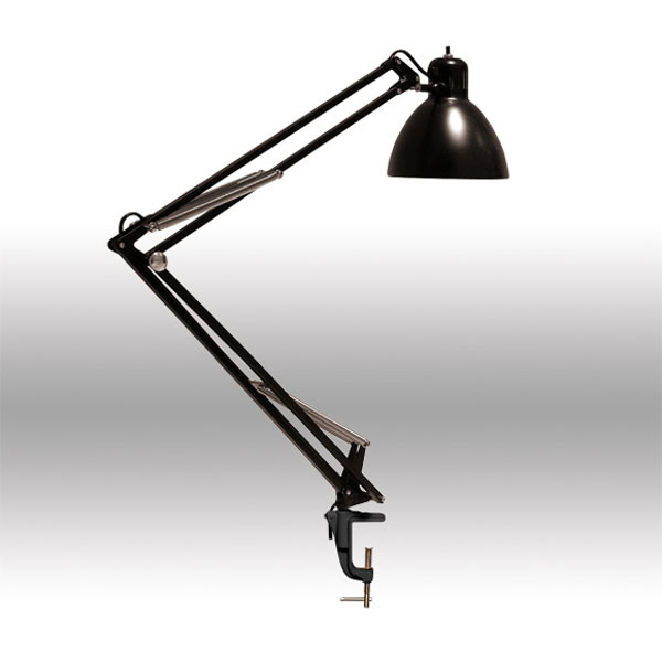
- To check the sensor, you can use the most ordinary table lamp with a metal lampshade. As noted above, room temperature allows you to withstand a voltage at the emitter of VT1 of about 6.8V, but if you increase it to 90⁰C, the voltage drops to 5.99V. For measurements, you can use a regular Chinese multimeter with a thermocouple type DT838.
- The comparator works as follows: if the voltage of the temperature sensor at the inverting input is higher than the voltage at the non-inverting input, then at the output it will be equal to the voltage of the power source - this will be a logical one. Therefore, VT2 opens and the relay turns on, moving the relay contacts to heating mode.
- Temperature sensor VT1 heats up as the heating circuit heats up and as the temperature rises, the voltage at the emitter decreases. At the moment when it drops slightly below the voltage that is set on the R7 engine, a logical zero is obtained, which leads to the transistor turning off and the relay turning off.
- At this time, no voltage is supplied to the boiler and the system begins to cool, which also entails the cooling of the VT1 sensor. This means that the voltage at the emitter increases and as soon as it crosses the limit set by R7, the relay starts again. This process will be repeated constantly.
- As you understand, the price of such a device is low, but it allows you to maintain the desired temperature at any temperature. weather conditions. This is very convenient in cases where there are no permanent residents in the room monitoring temperature conditions, or when people constantly replace each other and are also busy with work.