Hello everyone, today in our article we will look at how to make a soil moisture sensor with your own hands. Reason self-made This could be due to sensor wear (corrosion, oxidation), or simply the inability to purchase, a long wait and the desire to make something with your own hands. In my case, the desire to make the sensor myself was due to wear and tear; the fact is that the sensor probe, with a constant supply of voltage, interacts with the soil and moisture, as a result of which it oxidizes. For example, SparkFun sensors coat it with a special composition (Electroless Nickel Immersion Gold) to enhance the service life. Also, to extend the life of the sensor, it is better to supply power to the sensor only at the time of measurements.
One “fine” day I noticed that my irrigation system was moistening the soil unnecessarily; when checking the sensor, I removed the probe from the soil and this is what I saw:

Due to corrosion, additional resistance appears between the probes, as a result of which the signal becomes smaller and the arduino believes that the soil is dry. Since I am using an analog signal, I will not make a circuit with a digital output on the comparator to simplify the circuit.

The diagram shows a comparator for a soil moisture sensor; the part that converts the analog signal to a digital one is marked in red. The unmarked part is the part we need to convert humidity into an analog signal, and we will use it. Below I have given a diagram for connecting the probes to the arduino.

The left part of the diagram shows how the probes are connected to the arduino, and I showed the right part (with resistor R2) in order to show why the ADC readings change. When the probes are lowered into the ground, a resistance is formed between them (in the diagram I have shown it conventionally R2), if the soil is dry, then the resistance is infinitely large, and if it is wet, then it tends to 0. Since two resistances R1 and R2 form a voltage divider, and the middle point is the output (out a0), then the voltage at the output depends on the value of resistance R2. For example, if resistance R2=10Kom then the voltage will be 2.5V. You can solder the resistance on the wires so as not to make additional decouplings; for stability of the readings, you can add a 0.01 µF capacitor between the supply and out. The connection diagram is as follows:

Since we have dealt with the electrical part, we can move on to the mechanical part. For the manufacture of probes, it is better to use a material that is least susceptible to corrosion in order to prolong the life of the sensor. You can use stainless steel or galvanized metal, you can choose any shape, you can even use two pieces of wire. I chose “galvanized” for the probes; I used a small piece of getinax as a fixing material. It is also worth considering that the distance between the probes should be 5mm-10mm, but you should not do more. I soldered the sensor wires onto the ends of the galvanized sheet. Here's what we ended up with:


Didn't do it detailed photo report, everything is as simple as that. Well, here's a photo of it in action:

As I already indicated earlier, it is better to use the sensor only at the time of measurement. The best option switching on via a transistor switch, but since my current consumption was 0.4 mA, it can be switched on directly. To supply voltage during measurements, you can connect the contact of the VCC sensor to the PWM pin or use the digital output to supply a high (HIGH) level at the time of measurements, and then set it to low. It is also worth considering that after applying voltage to the sensor, you must wait some time for the readings to stabilize. Example via PWM:
Int sensor = A0; int power_sensor = 3;
void setup() (
// put your setup code here, to run once:
Serial.begin(9600);
analogWrite(power_sensor, 0);
}
void loop() (
delay(10000);
Serial.print("Suhost" : ");
Serial.println(analogRead(sensor));
analogWrite(power_sensor, 255);
delay(10000);
}
Thanks everyone for your attention!
The poet Andrei Voznesensky once said: “laziness is the engine of progress.” It is perhaps difficult to disagree with this phrase, because most electronic devices are created precisely for the purpose of making our daily lives easier, full of worries and all sorts of hectic affairs.
If you are reading this article now, then you are probably very tired of the process of watering flowers. After all, flowers are delicate creatures, you overwater them a little, you’re unhappy, you forget to water them for a day, that’s it, they’re about to fade. And how many flowers in the world have died just because their owners went on vacation for a week, leaving the poor green creatures to wither in a dry pot! It's scary to imagine.
It is to prevent such terrible situations that automatic watering systems were invented. A sensor is installed on the pot that measures soil moisture - it consists of stainless steel metal rods stuck into the ground at a distance of a centimeter from each other.
They are connected via wires to a circuit whose task is to open the relay only when the humidity drops below the set value and close the relay at the moment when the soil is saturated with moisture again. The relay, in turn, controls the pump, which pumps water from the reservoir directly to the root of the plant.
Sensor circuit


As is known, the electrical conductivity of dry and wet soil differs quite significantly; it is this fact that underlies the operation of the sensor. A 10 kOhm resistor and a section of soil between the rods form a voltage divider; their midpoint is connected directly to the input of the op-amp. The voltage is supplied to the other input of the op-amp from the midpoint of the variable resistor, i.e. it can be adjusted from zero to supply voltage. With its help, the switching threshold of the comparator, in the role of which the op-amp operates, is set. As soon as the voltage at one of its inputs exceeds the voltage at the other, the output will be logical “1”, the LED will light up, the transistor will open and turn on the relay. You can use any transistor, PNP structure, suitable for current and voltage, for example, KT3107 or KT814. Operational amplifier TL072 or any similar one, for example RC4558. A low-power diode, for example, 1n4148, should be placed in parallel with the relay winding. The supply voltage of the circuit is 12 volts.


Due to the long wires from the pot to the board itself, a situation may arise that the relay does not switch clearly, but begins to click at the frequency of the alternating current in the network, and only after some time is set in the open position. To eliminate this bad phenomenon, you should place an electrolytic capacitor with a capacity of 10-100 μF in parallel with the sensor. Archive with the board. Happy building! Author - Dmitry S.
Discuss the article SOIL MOISTURE SENSOR DIAGRAM
Automation significantly simplifies the life of the owner of a greenhouse or personal plot. An automatic irrigation system will save you from monotonous repetitive work, and an earth moisture sensor will help you avoid excess water - with my own hands It is not that difficult to assemble such a device. The laws of physics come to the aid of the gardener: moisture in the soil becomes a conductor of electrical impulses, and the more there is, the lower the resistance.
As humidity decreases, resistance increases, and this helps to track the optimal watering time.
Design and operating principle of a humidity sensor
The design of the earth humidity sensor consists of two conductors, which are connected to a low-power source of energy; there must be a resistor in the circuit. As the amount of liquid in the space between the electrodes increases, the resistance decreases and the current increases.
The moisture dries - the resistance increases, the current decreases.
Because the electrodes will be in a wet environment, it is recommended to turn them on via a key in order to reduce the destructive effects of corrosion. During idle times, the system is switched off and starts only to check the humidity by pressing a button.
Ground moisture sensors can be installed in greenhouses - they provide control over automatic watering, so the system can function largely without human intervention. In this case, the set will always be in working condition, but the condition of the electrodes will need to be monitored so that they do not deteriorate due to corrosion. Similar devices can be installed on lawns and garden beds in the open air - they will allow you to instantly obtain the necessary information.
At the same time, the totality is revealed much more correctly than a simple tactile sensation. If a person calculates that the soil is completely dry, the sensor will demonstrate up to 100 units of soil moisture (when assessed in a decimal aggregate), immediately after watering this value increases to 600-700 units.
Then the sensor will allow you to monitor changes in moisture content in the soil.
If the sensor is intended to be used outdoors, its upper part must be carefully sealed to prevent information distortion. To do this, it can be coated with moisture-proof epoxy resin.
Assembling a humidity sensor with your own hands
The sensor design plans as follows:
- The main part is two electrodes, the diameter of which is 3-4 mm; they are attached to a base made of textolite or other material protected from corrosion.
- At one end of the electrodes it is necessary to cut a thread, otherwise they are made pointed for more ergonomic immersion in the ground.
- Holes are drilled in the PCB plate into which the electrodes are screwed; they must be secured with nuts and washers.
- It is necessary to place outgoing wires under the washers, after which the electrodes are insulated. The length of the electrodes, which will be immersed in the ground, is about 4-10 cm, depending on the container used or the open bed.
- To operate the sensor, a current source of 35 mA is required; the combination requires a voltage of 5V. Depending on the amount of liquid in the ground, the range of the returned signal will be 0-4.2 V. Resistance losses will show the amount of water in the ground.
- The earth humidity sensor is connected via 3 wires to the processor; for this purpose it is possible to buy, for example, an Arduino. The controller will allow you to connect the system to a buzzer to give a sound signal when the soil moisture decreases excessively, or to an LED; the brightness of the lighting will change with changes in the operation of the sensor.
This homemade device can become part of the automatic watering system Smart home, for example, using the MegD-328 Ethernet controller. The web interface shows the humidity level in a 10-bit aggregate: the range from 0 to 300 shows that the soil is completely dry, 300-700 - there is enough moisture in the ground, more than 700 - the soil is wet and no watering is needed.
The design, consisting of a controller, relay and battery, is removed into any suitable housing, for which any plastic box can be adapted.
Using a humidity sensor at home will be very simple and at the same time reliable.
Areas of application of the humidity sensor
The use of the soil moisture sensor is possible in a wide variety of ways. Most often they are used in combinations of automatic watering and manual watering of plants:
- They can be installed in flower pots, if the plants are sensitive to the water level in the soil. When it comes to succulents, for example, cacti, you need to use long electrodes that will react to changes in the humidity level specifically at the roots. In addition, they can be used for other plants and violets with fragile root systems. Connecting to an LED will allow you to determine when it is time to water.
- They are indispensable for organizing watering plants in a greenhouse. Based on a similar principle, air humidity sensors are also planned, which are necessary to put the plant spraying system into operation. All this will allow you to automatically provide normal level and watering plants with atmospheric humidity.
- At the dacha, the use of sensors will make it possible not to remember the time of watering each bed; electrical engineering itself will tell you about the amount of water in the soil. This will prevent excessive watering if there was a rainstorm relatively recently.
- The use of sensors is very convenient in some second cases. For example, they will allow monitoring soil moisture in the basement and under the house near the foundation. In an apartment, it can be installed under the sink: if the pipe starts to drip, the automation will immediately tell you about it, and it will be possible to avoid subsequent repairs and flooding of neighbors.
- A simple sensor device will allow you to completely equip all problem areas of the house and garden with a warning system in just a couple of days. If the electrodes are long enough, they can be used to control the water level, for example, in an unnatural small reservoir.
Independent production of the sensor will help equip your home with an automatic control system at minimal cost.
Factory-made components are easy to buy online or in a special store; a large part of the devices can be assembled from materials that can always be found in the home of an electrical engineering enthusiast.
Do-it-yourself soil moisture sensor. AVR newbie.
DIY soil moisture sensor. AVR newbie.
The device that measures humidity levels is called a hygrometer or simply a humidity sensor. IN everyday life humidity is an important parameter, and often not only for ordinary life, but also for various equipment, and for agriculture (soil moisture) and much more.
In particular, our well-being depends a lot on the degree of air humidity. Particularly sensitive to humidity are weather-dependent people, as well as people suffering from hypertension, bronchial asthma, diseases of the cardiovascular system.
Even in very dry air healthy people feel discomfort, drowsiness, itching and irritation of the skin. Dry air can often cause illness respiratory system, starting with acute respiratory infections and ARVI, and even ending with pneumonia.
At enterprises, air humidity can affect the safety of products and equipment, and in agriculture clearly the influence of soil moisture on fertility, etc. This is where the use of humidity sensors - hygrometers.
Some technical devices are initially calibrated to strictly required values, and sometimes in order to fine-tune the device, it is important to have the exact humidity value in environment.
Humidity can be measured by several of the possible quantities:
To determine the humidity of both air and other gases, measurements are carried out in grams per cubic meter when talking about the absolute value of humidity, or in RH units when talking about relative humidity.
For measuring the humidity of solids or liquids, measurements as a percentage of the mass of the test samples are suitable.
To determine the moisture content of poorly mixed liquids, the units of measurement will be ppm (how many parts of water are in 1,000,000 parts of the weight of the sample).
According to the principle of operation, hygrometers are divided into:
capacitive;
resistive;
thermistor;
optical;
electronic.
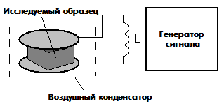
Capacitive hygrometers, in their simplest form, are capacitors with air as a dielectric in the gap. It is known that the dielectric constant of air is directly related to humidity, and changes in the humidity of the dielectric lead to changes in the capacitance of the air capacitor.
More difficult option capacitive sensor humidity in the air gap contains a dielectric with a dielectric constant that can vary greatly under the influence of humidity. This approach makes the quality of the sensor better than simply with air between the capacitor plates.

The second option is well suited for measuring water content in solids. The object under study is placed between the plates of such a capacitor, for example, the object can be a tablet, and the capacitor itself is connected to oscillatory circuit and to an electronic generator, while the natural frequency of the resulting circuit is measured, and from the measured frequency the capacitance obtained by introducing the test sample is “calculated”.
Undoubtedly, this method It also has some disadvantages, for example, if the sample humidity is below 0.5%, it will be inaccurate, in addition, the sample being measured must be cleaned of particles with high dielectric constant, and the shape of the sample is also important during the measurement process; it should not change during the study .

The third type of capacitive humidity sensor is the capacitive thin film hygrometer. It includes a substrate on which two comb electrodes are applied. In this case, comb electrodes play the role of plates. For the purpose of temperature compensation, two additional temperature sensors are additionally introduced into the sensor.

Such a sensor includes two electrodes that are deposited on a substrate, and on top of the electrodes themselves is a layer of material that has a fairly low resistance, which, however, varies greatly depending on humidity.

Aluminum oxide may be a suitable material for the device. This oxide absorbs well from external environment water, while its resistivity changes noticeably. As a result, the total resistance of the measurement circuit of such a sensor will depend significantly on humidity. Thus, the level of humidity will be indicated by the amount of current flowing. The advantage of sensors of this type is their low price.
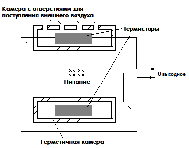
A thermistor hygrometer consists of a pair of identical thermistors. By the way, let us recall that this is a nonlinear electronic component, the resistance of which strongly depends on its temperature.
One of the thermistors included in the circuit is placed in a sealed chamber with dry air. And the other is in a chamber with holes through which air with characteristic humidity enters it, the value of which needs to be measured. The thermistors are connected in a bridge circuit, voltage is applied to one of the diagonals of the bridge, and readings are taken from the other diagonal.
In the case when the voltage at the output terminals is zero, the temperatures of both components are equal, therefore the humidity is the same. If a non-zero voltage is obtained at the output, this indicates the presence of a humidity difference in the chambers. Thus, the humidity is determined from the voltage obtained during measurements.
An inexperienced researcher may have a fair question: why does the temperature of the thermistor change when it interacts with moist air? The thing is that as humidity increases, water begins to evaporate from the thermistor body, while the temperature of the body decreases, and the higher the humidity, the more intense the evaporation occurs, and the faster the thermistor cools.
4) Optical (condensation) humidity sensor
This type of sensor is the most accurate. The operation of an optical humidity sensor is based on a phenomenon related to the concept of “dew point”. At the moment the temperature reaches the dew point, the gaseous and liquid phases are in thermodynamic equilibrium.
So, if you take glass and install it in a gaseous environment, where the temperature at the time of research is above the dew point, and then begin the process of cooling this glass, then at a specific temperature value water condensate will begin to form on the surface of the glass, this water vapor will begin to turn into the liquid phase . This temperature will be the dew point.
So, the dew point temperature is inextricably linked and depends on parameters such as humidity and pressure in the environment. As a result, having the ability to measure pressure and dew point temperature, it will be easy to determine humidity. This principle serves as the basis for the functioning of optical humidity sensors.

The simplest circuit of such a sensor consists of an LED shining on a mirror surface. The mirror reflects the light, changing its direction, and directing it to the photodetector. In this case, the mirror can be heated or cooled using a special high-precision temperature control device. Often such a device is a thermoelectric pump. Of course, a sensor is installed on the mirror to measure temperature.
Before starting measurements, the mirror temperature is set to a value that is obviously higher than the dew point temperature. Next, the mirror is gradually cooled. At the moment when the temperature begins to cross the dew point, drops of water will immediately begin to condense on the surface of the mirror, and the light beam from the diode will break due to them, dissipate, and this will lead to a decrease in the current in the photodetector circuit. Through feedback the photodetector interacts with the mirror temperature regulator.
So, based on the information received in the form of signals from the photodetector, the temperature controller will keep the temperature on the surface of the mirror exactly equal to the dew point, and the temperature sensor will show the temperature accordingly. Thus, at known pressure and temperature, the main humidity indicators can be accurately determined.
The optical humidity sensor has the highest accuracy, unattainable by other types of sensors, plus the absence of hysteresis. The disadvantage is the most high price of all, plus high power consumption. In addition, it is necessary to ensure that the mirror is clean.
The operating principle of an electronic air humidity sensor is based on changing the concentration of electrolyte covering any electrical insulating material. There are such devices with automatic heating with reference to the dew point.
Often the dew point is measured over a concentrated solution of lithium chloride, which is very sensitive to minimal changes in humidity. For maximum convenience, such a hygrometer is often additionally equipped with a thermometer. This device has high accuracy and low error. It is capable of measuring humidity regardless of the ambient temperature.

Popular and simple electronic hygrometers in the form of two electrodes that are simply stuck into the soil, controlling its humidity according to the degree of conductivity depending on this very humidity. Such sensors are popular among fans because you can easily set up automatic watering of a garden bed or flower in a pot, in case you don’t have time to water manually or it’s not convenient.
Before you buy a sensor, consider what you will need to measure, relative or absolute humidity, air or soil, what the expected measurement range is, whether hysteresis is important, and what accuracy is needed. The most accurate sensor is optical. Pay attention to the IP protection class, the operating temperature range, depending on the specific conditions where the sensor will be used, whether the parameters are suitable for you.