Information is provided for educational purposes only!
The site administrator is not responsible for the possible consequences of using the information provided.
CHARGED CAPACITORS DEADLY DANGEROUS!
Electromagnetic gun (Gauss gun, English. coilgun) in its classical version is a device that uses the property of ferromagnets to be drawn into a region of stronger magnetic field to accelerate the ferromagnetic “projectile”.
My gauss gun:
top view: 
side view: 
1 - connector for connecting a remote release
2 - “battery charge/work” switch
3 - connector for connecting to a computer sound card
4 - capacitor charge/shot switch
5 - emergency capacitor discharge button
6 - "Battery charge" indicator
7 - "Work" indicator
8 - "Charge of capacitor" indicator
9 - "Shot" indicator
Diagram of the power part of the Gauss gun:

1 - trunk
2 - protective diode
3 - coil
4 - IR LEDs
5 - IR phototransistors
The main design elements of my electromagnetic gun:
battery
-
I use two lithium-ion batteries SANYO UR18650A 18650 format from a laptop with a capacity of 2150 mAh, connected in series:
...
The maximum discharge voltage of these batteries is 3.0 V.
voltage converter for powering control circuits -
The voltage from the batteries is supplied to a step-up voltage converter on the 34063 chip, which increases the voltage to 14 V. Then the voltage is supplied to the converter to charge the capacitor, and stabilized to 5 V by the 7805 chip to power the control circuit.
voltage converter for charging the capacitor
-
boost converter based on 7555 timer and MOSFET-transistor ;
- This N-channel MOSFET- transistor in housing TO-247 with the maximum permissible drain-source voltage VDS= 500 volts, maximum pulsed drain current I D= 56 amperes and a typical drain-to-source resistance value of open state RDS(on)= 0.33 ohm. 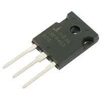
The inductance of the converter choke affects its operation:
too low inductance determines the low charging rate of the capacitor;
too high an inductance can lead to core saturation.
As a pulse generator ( oscillator circuit) for converter ( boost converter) you can use a microcontroller (for example, the popular Arduino), which will allow implementing pulse width modulation (PWM, PWM) to control the duty cycle of pulses.
capacitor (coil cap(acitor)) -
electrolytic capacitor for a voltage of several hundred volts.
Previously, I used a K50-17 capacitor from a Soviet external flash with a capacity of 800 μF for a voltage of 300 V: 
The disadvantages of this capacitor are, in my opinion, the low operating voltage, increased leakage current (leads to longer charging) and possibly increased capacitance.
Therefore, I switched to using imported modern capacitors: 
SAMWHA for voltage 450 V with a capacity of 220 μF series HC. HC- this is a standard series of capacitors SAMWHA, there are other series: HE- operating in a wider temperature range, H.J.- with increased lifetime;
PEC for a voltage of 400 V with a capacity of 150 μF.
I also tested a third capacitor for a voltage of 400 V with a capacity of 680 μF, purchased from an online store dx.com -
In the end I settled on using a capacitor PEC for a voltage of 400 V with a capacity of 150 µF.
For a capacitor, its equivalent series resistance ( ESR).
switch -
power switch S.A. designed for switching a charged capacitor C per reel L:
either thyristors or IGBT-transistors:
thyristor
-
I use power thyristor ТЧ125-9-364 with cathode control
appearance
dimensions  - high-speed pin thyristor: “125” means the maximum permissible effective current (125 A); "9" means the class of the thyristor, i.e. repetitive pulse voltage in hundreds of volts (900 V).
Using a thyristor as a key requires selecting the capacitance of the capacitor bank, since a prolonged current pulse will lead to the retraction of a projectile that has passed the center of the coil back - " suck-back effect".
IGBT transistor -
use as a key IGBT-transistor allows not only to close, but also to open the coil circuit. This allows the current (and the coil's magnetic field) to be interrupted after the projectile passes through the center of the coil, otherwise the projectile would be pulled back into the coil and therefore slowed down. But opening the coil circuit (a sharp decrease in the current in the coil) leads to the appearance of a high voltage pulse on the coil in accordance with the law of electromagnetic induction $u_L = (L ((di_L) \over (dt)))$. To protect the key -IGBT-transistor, additional elements must be used: 
VD TVs- diode ( TVS diode), creating a path for the current in the coil when the key is opened and dampening a sharp voltage surge on the coil
Rdis- discharge resistor ( discharge resistor) - provides attenuation of the current in the coil (absorbs the energy of the magnetic field of the coil)
C rsringing suppression capacitor), preventing the occurrence of overvoltage pulses on the key (can be supplemented with a resistor, forming RC-snubber)
I used IGBT-transistor IRG48BC40F from the popular series IRG4.
coil -
The coil is wound on a plastic frame with copper wire. The ohmic resistance of the coil is 6.7 ohms. The width of multilayer winding (pile) $b$ is 14 mm, there are about 30 turns in one layer, the maximum radius is about 12 mm, the minimum radius $D$ is about 8 mm (average radius $a$ is about 10 mm, height $c $ - about 4 mm), wire diameter - about 0.25 mm.
A diode is connected in parallel to the coil UF5408 (suppression diode) (peak current 150 A, peak reverse voltage 1000 V), dampening the self-induction voltage pulse when the current in the coil is interrupted.
barrel
-
Made from the body of a ballpoint pen.
projectile -
The parameters of the test projectile are a piece of nail with a diameter of 4 mm (barrel diameter ~ 6 mm) and a length of 2 cm (the volume of the projectile is 0.256 cm 3 and the mass $m$ = 2 grams, if we take the steel density to be 7.8 g/cm 3 ). I calculated the mass by imagining the projectile as a combination of a cone and a cylinder. 
The projectile material must be ferromagnetic.
Also, the projectile material should have as much high magnetic saturation threshold - saturation induction value $B_s$. One of best options is ordinary soft magnetic iron (for example, ordinary non-hardened steel St. 3 - St. 10) with a saturation induction of 1.6 - 1.7 Tesla. Nails are made from low-carbon, thermally untreated steel wire(steel grades St. 1 KP, St. 2 KP, St. 3 PS, St. 3 KP).
Steel designation:
Art.- carbon steel of ordinary quality;
0 - 10
- percentage of carbon increased by 10 times. As the carbon content increases, the saturation induction $B_s$ decreases.
And the most effective is the alloy " permendur", but it is too exotic and expensive. This alloy consists of 30-50% cobalt, 1.5-2% vanadium and the rest is iron. Permendur has the highest saturation induction $B_s$ of all known ferromagnets up to 2.43 Tesla.
It is also desirable that the projectile material have as much low conductivity. This is due to the fact that eddy currents arising in an alternating magnetic field in the conducting rod lead to energy losses.
Therefore, as an alternative to nail cutting projectiles, I tested a ferrite rod ( ferrite rod), taken from the inductor from the motherboard: 
Similar coils are also found in computer power supplies: 
Appearance of a ferrite core coil: 
Rod material (probably nickel-zinc ( Ni-Zn) (analogue of domestic brands of ferrite NN/VN) ferrite powder) is dielectric, which eliminates the occurrence of eddy currents. But the disadvantage of ferrite is the low saturation induction $B_s$ ~ 0.3 Tesla.
The length of the rod was 2 cm: 
The density of nickel-zinc ferrites is $\rho$ = 4.0 ... 4.9 g/cm 3 .
Projectile gravity
The calculation of the force acting on a projectile in a Gauss gun is complex task.
There are several examples of calculating electromagnetic forces.
The force of attraction of a piece of ferromagnet to a solenoid coil with a ferromagnetic core (for example, a relay armature to a coil) is determined by the expression $F = (((((w I))^2) \mu_0 S) \over (2 ((\delta)^ 2)))$, where $w$ is the number of turns in the coil, $I$ is the current in the coil winding, $S$ is the cross-sectional area of the coil core, $\delta$ is the distance from the coil core to the attracted piece. In this case, we neglect the magnetic resistance of ferromagnets in the magnetic circuit.
The force drawing a ferromagnet into the magnetic field of a coreless coil is given by $F = ((w I) \over 2) ((d\Phi) \over (dx))$.
In this formula, $((d\Phi) \over (dx))$ is the rate of change of the magnetic flux of the coil $\Phi$ when moving a piece of ferromagnet along the axis of the coil (changing the coordinate $x$), this value is quite difficult to calculate. The above formula can be rewritten as $F = (((I)^2) \over 2) ((dL) \over (dx))$, where $((dL) \over (dx))$ is the rate of change coil inductance $L$.
The procedure for firing a shot from a gauss gun
Before firing, the capacitor must be charged to a voltage of 400 V. To do this, turn on the switch (2) and move the switch (4) to the “CHARGE” position. To indicate voltage, a level indicator from a Soviet tape recorder is connected to the capacitor through a voltage divider. For emergency discharge of the capacitor without connecting the coil, a 6.8 kOhm resistor with a power of 2 W is used, connected using a switch (5) to the capacitor. Before firing, you must move the switch (4) to the “SHOT” position. To avoid the influence of contact bounce on the formation of a control pulse, the “Shot” button is connected to the anti-bounce circuit on the switching relay and microcircuit 74HC00N. From the output of this circuit, the signal triggers a one-shot device, which produces a single pulse of adjustable duration. This pulse arrives through an optocoupler PC817 to the primary winding of the pulse transformer, which provides galvanic isolation of the control circuit from the power circuit. The pulse generated on the secondary winding opens the thyristor and the capacitor is discharged through it into the coil.
The current flowing through the coil during discharge creates a magnetic field that draws in the ferromagnetic projectile and gives the projectile a certain initial speed. After leaving the barrel, the projectile continues to fly by inertia. It should be taken into account that after the projectile passes through the center of the coil, the magnetic field will slow down the projectile, so the current pulse in the coil should not be prolonged, otherwise this will lead to a decrease in the initial speed of the projectile.
For remote control a button is connected to the connector (1): 
Determining the speed of a projectile leaving the barrel
When fired, muzzle velocity and energy are highly dependent from the initial position of the projectile in the trunk.
To set the optimal position, it is necessary to measure the speed at which the projectile leaves the barrel. For this I used an optical speed meter - two optical sensors (IR LEDs VD1, VD2+ IR phototransistors VT1, VT2) are placed in the trunk at a distance of $l$ = 1 cm from each other. When flying, the projectile covers the phototransistors from the radiation of the LEDs, and the comparators on the chip LM358N generate a digital signal: 

When the light flux of sensor 2 (closest to the coil) is blocked, red (" RED") LED, and when sensor 1 is blocked - green (" GREEN").
This signal is converted to a level of tenths of a volt (dividers from resistors R1,R3 And R2,R4) and is fed to two channels of the linear (not microphone!) input of the computer sound card using a cable with two plugs - a plug connected to the Gaussian connector, and a plug plugged into the socket of the computer sound card:
voltage divider:
LEFT- left channel; RIGHT- right channel; GND- "Earth"
plug connected to the gun:
5 - left channel; 1 - right channel; 3 - "ground"
plug connected to the computer:
1 - left channel; 2 - right channel; 3 - "ground"
It is convenient to use for signal processing free program Audacity().
Since on each sound card input channel a capacitor is connected in series with the rest of the circuit, the sound card input is actually R.C.-chain, and the signal recorded by the computer has a smoothed form: 
Characteristic points on the graphs:
1 - flight of the front part of the projectile past sensor 1
2 - flight of the front part of the projectile past sensor 2
3 - flight of the rear part of the projectile past sensor 1
4 - flight of the rear part of the projectile past sensor 2
I determine the initial velocity of the projectile by the time difference between points 3 and 4, taking into account that the distance between the sensors is 1 cm.
In the given example, with a digitizing frequency $f$ = 192000 Hz for the number of samples $N$ = 160, the projectile speed $v = ((l f) \over (N)) = ((1920) \over 160)$ was 12 m/s .
The speed of a projectile leaving the barrel depends on its initial position in the barrel, specified by the displacement of the rear part of the projectile from the edge of the barrel $\Delta$: 
For each battery capacity $C$, the optimal projectile position ($\Delta$ value) is different.
For the projectile described above and a battery capacity of 370 uF, I got the following results:
With a battery capacity of 150 µF the results were as follows:
The maximum projectile speed was $v$ = 21.1 m/s (at $\Delta$ = 10 mm), which corresponds to an energy of ~ 0.5 J
-
When testing a ferrite rod projectile, it turned out that it requires a much deeper location in the barrel (a much larger $\Delta$ value).
Gun laws
In the Republic of Belarus, products with muzzle energy ( muzzle energy) no more than 3 J
purchased without appropriate permission and are not registered.
IN Russian Federation products with muzzle energy less than 3 J
are not considered weapons.
In the UK, products with muzzle energy are not considered weapons. no more than 1.3 J.
Determination of capacitor discharge current
To determine the maximum discharge current of a capacitor, you can use a graph of the voltage across the capacitor during discharge. To do this, you can connect to a connector to which the voltage on the capacitor, reduced by $n$ = 100 times, is supplied through a divider. Capacitor discharge current $i = (n) \cdot (C \cdot ((du) \over (dt))) = (((m_u) \over (m_t)) C tg \alpha)$, where $\alpha$ - the angle of inclination of the tangent to the capacitor voltage curve at a given point.
Here is an example of such a discharge voltage curve on a capacitor: 
In this example $C$ = 800 µF, $m_u$ = 1 V/div, $m_t$ = 6.4 ms/div, $\alpha$ = -69.4°, $tg\alpha = -2 .66 $, which corresponds to the current at the beginning of the discharge $i = (100) \cdot (800) \cdot (10^(-6)) \cdot (1 \over (6.4 \cdot (10^(-3) ))) \cdot (-2.66) = -33.3$ amperes.
To be continued
Once I was playing the well-known game Stalker, and I saw this unusual weapon- Gauss gun. She had the best weapon parameters. On the Internet I found an article on how to make this very weapon. But as luck would have it, I didn’t have the parts to make a gauss cannon.
I found a gauss gun circuit from 220 volts and looked at the operation of the gun, began to develop my own gauss gun circuit, using available elements and powered by 6-15 volts.
I decided to use the voltage converter from the circuit, but I changed the circuit a little and the transformer will be different. The result was the following diagram:
The rectangular pulse generator is assembled on transistors VT1-VT2; it generates high-frequency pulses that pass through the primary winding of the transformer and generate high-voltage pulses on the secondary winding, which are rectified by the diode VD1 and the capacitor C1 is charged to a voltage of 250-350 Volts.
The transformer has a primary winding of 3-7 turns of 1mm wire. And the secondary winding is 90-120 turns of wire 0.3-0.4 mm.
We wind the transformer on the core from a transformer from any switching power supply. The main thing is that the windings fit.
Without load, with a power supply of 12 volts, the output is about 700-900 volts. After the diode, 380-450 volts.
Making a coil (solenoid) is not difficult:
We wind the coil turn to turn with 0.6-0.8 mm wire with a total resistance of 3-5 Ohms (with a resistance of 1.5 Ohms the result is much better with a bank of capacitors 1000 MF * 200 V) on a plastic tube with a gap of 0.4-0.7 cm.
To control the voltage, connect a voltmeter in parallel with the capacitor and when the capacitor is charged to the required voltage, disconnect the circuit from the power supply and insert the projectile near the coil into the tube (the projectile is a piece of nail 2-4 cm long and the diameter depends on the tube and on the flight range, choose it yourself)
We aim and press the SA1 switch. If the projectile gets stuck in the middle of the tube, or flies out a short distance, then try playing with the distance between the projectile and the coil.
A few photos:


Charging capacitors (from the battery is much faster, my power supply is weak)
I'm burning the light bulb from the converter.
ADDENDUM(09/17/2013)
A neon light should be added to indicate the charge of the capacitor. To correctly display the state of the capacitor, a voltage extender of 3 was made (to connect the neon to a *200 Volt capacitor.) To connect the capacitor to a different voltage, a different divider is needed.
Neonka - from a simple kettle at 220 Volts. Ignition threshold is 60-80 Volts.
Here is the connection diagram:

Resistors for 200 volts. At 200 volts, the light bulb lights up.
Here are some photos and videos:


List of radioelements
| Designation | Type | Denomination | Quantity | Note | Shop | My notepad |
|---|---|---|---|---|---|---|
| VT1 | Bipolar transistor | KT805AM | 1 | Any NPN is powerful | To notepad | |
| VT2 | Bipolar transistor | KT361A | 1 | Any low power PNP | To notepad | |
| VD1 | Rectifier diode | FR107 | 1 | HF 1000V | To notepad | |
| C1 | Capacitor | 0.1 µF | 1 | 25V | To notepad | |
| C2 | Electrolytic capacitor | 500-10000 uF | 1 | 350-450V | To notepad | |
| R1 | Resistor | 100 Ohm | 1 | 0.25W | To notepad | |
| R2 | Resistor |
We present the electromagnetic gun circuit based on the NE555 timer and the 4017B chip.
The operating principle of an electromagnetic (Gauss) gun is based on the rapid sequential actuation of electromagnets L1-L4, each of which creates an additional force that accelerates the metal charge. The NE555 timer sends pulses with a period of approximately 10 ms to the 4017 chip, the pulse frequency is signaled by LED D1.
When you press the PB1 button, the IC2 microcircuit with the same interval sequentially opens transistors TR1 to TR4, the collector circuit of which includes electromagnets L1-L4.
To make these electromagnets we need a copper tube 25 cm long and 3 mm in diameter. Each coil contains 500 turns of 0.315mm enamel coated wire. The coils must be made in such a way that they can move freely. The projectile is a piece of nail 3 cm long and 2 mm in diameter.
The gun can be powered either from a 25 V battery or from an AC mains.
By changing the position of the electromagnets we achieve the best effect; from the figure above it can be seen that the interval between each coil increases - this is due to the increase in the speed of the projectile.
This is, of course, not a real Gauss gun, but a working prototype, on the basis of which it is possible, by strengthening the circuit, to assemble a more powerful Gauss gun.
Other types of electromagnetic weapons.
In addition to magnetic mass accelerators, there are many other types of weapons that use electromagnetic energy to operate. Let's look at the most famous and common types.
Electromagnetic mass accelerators.
In addition to “Gauss guns”, there are at least 2 more types of mass accelerators - induction mass accelerators (Thompson coil) and rail mass accelerators, also known as “rail guns”.
 The operation of an induction mass accelerator is based on the principle of electromagnetic induction. In a flat winding, a rapidly increasing electric current, which causes an alternating magnetic field in the space around. A ferrite core is inserted into the winding, on the free end of which a ring of conductive material is put on. Under the influence of an alternating magnetic flux penetrating the ring, an electric current arises in it, creating a magnetic field in the opposite direction relative to the field of the winding. With its field, the ring begins to push away from the field of the winding and accelerates, flying off the free end of the ferrite rod. The shorter and stronger the current pulse in the winding, the more powerful the ring flies out.
 The rail mass accelerator functions differently. In it, a conducting projectile moves between two rails - electrodes (where it got its name - railgun), through which current is supplied.
The current source is connected to the rails at their base, so the current flows as if in pursuit of the projectile, and the magnetic field created around the current-carrying conductors is completely concentrated behind the conducting projectile. In this case, the projectile is a current-carrying conductor placed in a perpendicular magnetic field created by the rails. According to all the laws of physics, the projectile is subject to the Lorentz force, directed in the direction opposite to the place where the rails are connected and accelerating the projectile. There are a number of serious problems associated with the manufacture of a railgun - the current pulse must be so powerful and sharp that the projectile would not have time to evaporate (after all, a huge current flows through it!), but an accelerating force would arise, accelerating it forward. Therefore, the material of the projectile and the rail must have the highest possible conductivity, the projectile must have as little mass as possible, and the current source must have as much power and less inductance as possible. However, the peculiarity of the rail accelerator is that it is capable of accelerating ultra-low masses to extremely high speeds. In practice, the rails are made of oxygen-free copper coated with silver, aluminum bars are used as projectiles, a battery of high-voltage capacitors is used as a power source, and before entering the rails they try to give the projectile itself the highest possible initial speed, using pneumatic or fire guns.
In addition to mass accelerators, electromagnetic weapons include sources of powerful electromagnetic radiation such as lasers and magnetrons.
 Everyone knows the laser. It consists of a working fluid in which, when fired, an inverse population of quantum levels with electrons is created, a resonator to increase the range of photons inside the working fluid, and a generator that will create this very inverse population. In principle, population inversion can be created in any substance, and nowadays it is easier to say what lasers are NOT made of.
Lasers can be classified by working fluid: ruby, CO2, argon, helium-neon, solid-state (GaAs), alcohol, etc., by operating mode: pulsed, continuous, pseudo-continuous, can be classified by the number of quantum levels used: 3-level , 4-level, 5-level. Lasers are also classified according to the frequency of the generated radiation - microwave, infrared, green, ultraviolet, x-ray, etc. The laser efficiency usually does not exceed 0.5%, but now the situation has changed - semiconductor lasers (solid-state lasers based on GaAs) have an efficiency of over 30% and today can have an output power of up to 100(!) W, i.e. comparable to powerful “classical” ruby or CO2 lasers. In addition, there are gas-dynamic lasers, which are least similar to other types of lasers. Their difference is that they are capable of producing a continuous beam of enormous power, which allows them to be used for military purposes. In essence, a gas dynamic laser is jet engine, perpendicular to the gas flow in which the resonator is located. The hot gas leaving the nozzle is in a state of population inversion.
If you add a resonator to it, a multi-megawatt stream of photons will fly into space.
 Microwave guns - the main functional unit is a magnetron - a powerful source of microwave radiation. The disadvantage of microwave guns is that they are extremely dangerous to use, even compared to lasers - microwave radiation is highly reflected from obstacles and if fired indoors, literally everything inside will be irradiated! In addition, powerful microwave radiation is fatal to any electronics, which must also be taken into account.
And why, in fact, exactly the “Gauss gun”, and not Thompson disc launchers, railguns or beam weapons?
The fact is that of all types of electromagnetic weapons, it is the Gauss Gun that is the easiest to manufacture. In addition, it has a fairly high efficiency compared to other electromagnetic shooters and can operate at low voltages.
At the next most complex stage are induction accelerators - Thompson disc throwers (or transformers). Their operation requires slightly higher voltages than for a conventional Gaussian, then, perhaps, in terms of complexity are lasers and microwaves, and in the very last place is the railgun, which requires expensive construction materials, impeccable calculation and manufacturing accuracy, an expensive and powerful source energy (a battery of high-voltage capacitors) and many other expensive things.
In addition, the Gauss gun, despite its simplicity, has incredibly large scope for design solutions and engineering research - so this direction is quite interesting and promising.
DIY microwave gun
First of all, I warn you: this weapon is very dangerous; use the maximum degree of caution during manufacture and operation!

In short, I warned you. Now let's start manufacturing.
We take any microwave oven, preferably the lowest-power and cheapest one.

If it is burnt out, it does not matter - as long as the magnetron is working. Here is its simplified diagram and internal view.

1. Lighting lamp.
2. Ventilation holes.
3. Magnetron.
4. Antenna.
5. Waveguide.
6. Capacitor.
7. Transformer.
8. Control panel.
9. Drive.
10. Rotating tray.
11. Separator with rollers.
12. Door latch.

Next, we extract this same magnetron from there. The magnetron was developed as a powerful generator of electromagnetic oscillations in the microwave range for use in radar systems. Microwave ovens contain magnetrons with a microwave frequency of 2450 MHz. The operation of a magnetron uses the process of electron movement in the presence of two fields - magnetic and electric, perpendicular to each other. A magnetron is a two-electrode tube or diode containing a hot cathode that emits electrons and a cold anode. The magnetron is placed in an external magnetic field.
DIY Gauss gun
The magnetron anode has a complex monolithic structure with a system of resonators necessary to complicate the structure electric field inside the magnetron. The magnetic field is created by coils with current (electromagnet), between the poles of which a magnetron is placed. If there were no magnetic field, then the electrons flying out of the cathode with virtually no initial velocity would move in electric field along straight lines perpendicular to the cathode, and all would fall on the anode. In the presence of a perpendicular magnetic field, electron trajectories are bent by the Lorentz force.

At our radio market we sell used magnetrons for 15e.

This is a magnetron in cross-section and without a radiator.
Now you need to find out how to power it. The diagram shows that the required filament is 3V 5A and the anode is 3kV 0.1A. The indicated power values apply to magnetrons from weak microwaves, and for powerful ones they may be slightly higher. Modern magnetron power microwave ovens is about 700 W.

For the compactness and mobility of the microwave gun, these values can be reduced somewhat - as long as generation occurs. We will power the magnetron from a converter with a battery from a computer uninterruptible power supply.

The rated value is 12 volts 7.5 amperes. A few minutes of battle should be enough. The magnetron heat is 3V, obtained using the LM150 stabilizer chip.

It is advisable to turn on the heat a few seconds before turning on the anode voltage. And we take kilovolts to the anode from the converter (see diagram below).

Power to the filament and P210 is supplied by turning on the main toggle switch a few seconds before the shot, and the shot itself is fired with a button that supplies power to the master oscillator on the P217. The transformer data is taken from the same article, only we wind the Tr2 secondary with 2000 - 3000 turns of PEL0.2. From the resulting winding, the alternating current is fed to a simple half-wave rectifier.

A high-voltage capacitor and diode can be taken from the microwave, or, if not available, replaced with a 0.5 µF - 2 kV diode - KTs201E.
To direct the radiation and cut off the reverse lobes (so that it doesn’t get caught), we place the magnetron in the horn. To do this, we use a metal horn from school bells or stadium speakers. As a last resort, you can take a cylindrical liter paint can.


The entire microwave gun is placed in a housing made of a thick pipe with a diameter of 150-200 mm.

Well, the gun is ready. It can be used to burn out on-board computers and car alarms, burn out brains and televisions evil neighbors, hunting for running and flying creatures. I hope you never launch this microwave weapon - for your own safety.

Compiled by: Patlakh V.V.
http://patlah.ru
ATTENTION!

Gauss cannon (Gauss rifle)

Other names: Gauss gun, Gauss gun, Gauss rifle, Gauss gun, accelerating rifle.
The Gauss rifle (or its larger variant, the Gauss gun), like the railgun, is an electromagnetic weapon.
Gauss gun
At the moment, there are no military industrial samples, although a number of laboratories (mostly amateur and university) continue to persistently work on the creation of these weapons. The system is named after the German scientist Carl Gauss (1777-1855). I personally cannot understand why the mathematician was so frightened (I still can’t, or rather, I don’t have the relevant information). Gauss had much less to do with the theory of electromagnetism than, for example, Oersted, Ampere, Faraday or Maxwell, but, nevertheless, the gun was named in his honor. The name stuck, and therefore we will use it too.

Operating principle:
A Gauss rifle consists of coils (powerful electromagnets) mounted on a barrel made of dielectric. When current is applied, the electromagnets are turned on one after another for a short moment in the direction from the receiver to the barrel. They take turns attracting a steel bullet (a needle, a dart or a projectile, if we talk about a cannon) and thereby accelerate it to significant speeds.
Advantages of the weapon:
1. Lack of cartridge. This allows you to significantly increase the magazine capacity. For example, a magazine that holds 30 rounds can load 100-150 bullets.
2. High rate of fire. Theoretically, the system allows you to begin accelerating the next bullet even before the previous one has left the barrel.
3. Silent shooting. The design of the weapon itself allows you to get rid of most of the acoustic components of the shot (see reviews), so shooting from a gauss rifle looks like a series of barely audible pops.
4. No unmasking flash. This property is especially useful at night.
5. Low recoil. For this reason, when firing, the barrel of the weapon practically does not lift up, and therefore the accuracy of the fire increases.
6. Reliability. The Gauss rifle does not use cartridges, and therefore the question of low-quality ammunition immediately disappears. If, in addition to this, we remember the absence of a firing mechanism, then the very concept of “misfire” can be forgotten like a bad dream.
7. Increased wear resistance. This property is due to the small number of moving parts, low loads on components and parts when firing, and the absence of gunpowder combustion products.
8. Possibility of use both in outer space and in atmospheres that suppress the combustion of gunpowder.
9. Adjustable bullet speed. This function allows, if necessary, to reduce the speed of the bullet below sound. As a result, the characteristic pops disappear, and the Gauss rifle becomes completely silent, and therefore suitable for secret special operations.
Weapon disadvantages:
Among the disadvantages of Gauss rifles, the following are often cited: low efficiency, high energy consumption, large weight and dimensions, long recharging time for capacitors, etc. I want to say that all these problems are due only to the level of modern technology development. In the future, when creating compact and powerful power supplies, when using new construction materials and superconductors, the Gauss gun can truly become a powerful and effective weapon.
In literature, of course, fantastic literature, William Keith armed the legionnaires with a gauss rifle in his “Fifth Foreign Legion” series. (One of my favorite books!) It was also in service with the militarists from the planet Klisand, to which Jim di Gris landed in Harrison’s novel “Revenge of the Stainless Steel Rat.” They say that Gausovka is also found in books from the S.T.A.L.K.E.R. series, but I have only read five of them. I didn’t find anything like that there, and I won’t speak for others.
As for my personal work, in my new novel “Marauders” I gave a Tula-made Metel-16 gauss carbine to my main character Sergei Korn. True, he owned it only at the beginning of the book. After all main character after all, which means he deserves a more impressive gun.
Oleg Shovkunenko
Reviews and comments:
Alexander 12/29/13
According to point 3, a shot with supersonic bullet speed will be loud in any case. For this reason, special subsonic cartridges are used for silent weapons.
According to point 5, recoil will be inherent in any weapon that shoots “material objects” and depends on the ratio of the masses of the bullet and the weapon, and the impulse of the force accelerating the bullet.
According to paragraph 8, no atmosphere can affect the combustion of gunpowder in a sealed cartridge. In outer space, firearms will also fire.
The problem can only be mechanical stability weapon parts and lubricant properties at ultra-low temperatures. But this issue can be resolved, and back in 1972, test firing was carried out in outer space from an orbital cannon from the military orbital station OPS-2 (Salyut-3).
Oleg Shovkunenko
Alexander, it’s good that you wrote it.
To be honest, I made a description of the weapon based on my own understanding of the topic. But maybe I was wrong about something. Let's figure it out together point by point.
Point No. 3. "Silent shooting."
As far as I know, the sound of a shot from any firearm consists of several components:
1) The sound, or better yet, the sounds of the weapon mechanism operating. This includes the impact of the firing pin on the capsule, the clanging of the bolt, etc.
2) The sound created by the air filling the barrel before the shot. It is displaced by both the bullet and the powder gases seeping through the rifle channels.
3) The sound that the powder gases themselves create during sudden expansion and cooling.
4) Sound created by an acoustic shock wave.
The first three points do not apply to Gaussian at all.
I foresee a question about air in the barrel, but in a Gauss-vintage barrel it is not at all necessary to be solid and tubular, which means the problem disappears by itself. So that leaves point number 4, which is exactly what you, Alexander, are talking about. I want to say that the acoustic shock wave is far from the loudest part of the shot. Silencers of modern weapons practically do not fight it at all. And yet, a firearm with a silencer is still called silent. Consequently, the Gaussian can also be called noiseless. By the way, thank you so much for reminding me. I forgot to mention among the advantages of the Gauss gun the ability to adjust the speed of the bullet. After all, it is possible to set a subsonic mode (which will make the weapon completely silent and intended for covert actions in close combat) and supersonic (this is for real war).
Point No. 5. "Almost complete absence return."
Of course, the gas gun also has recoil. Where would we be without her?! The law of conservation of momentum has not yet been canceled. Only the operating principle of a gauss rifle will make it not explosive, as in a firearm, but rather stretched out and smooth, and therefore much less noticeable to the shooter. Although, to be honest, these are just my suspicions. I've never fired a gun like this before :))
Point No. 8. “Possibility of use as in outer space...”.
Well, I didn’t say anything at all about the impossibility of using firearms in outer space. Only it will need to be remade in such a way, so many technical problems will need to be solved that it will be easier to create a gauss gun :)) As for planets with specific atmospheres, the use of firearms on them can indeed be not only difficult, but also unsafe. But this is already from the fantasy section, in fact, which is what your humble servant is doing.
Vyacheslav 04/05/14
Thanks for the interesting story about weapons. Everything is very accessible and laid out on the shelves. I would also like a diagram for greater clarity.
Oleg Shovkunenko
Vyacheslav, I inserted the schematic, as you asked).
interested 02.22.15
“Why a Gaus rifle?” - Wikipedia says that because he laid the foundations of the theory of electromagnetism.
Oleg Shovkunenko
Firstly, based on this logic, the aerial bomb should have been called “Newton’s Bomb”, because it falls to the ground, obeying the Law of Universal Gravitation. Secondly, in the same Wikipedia, Gauss is not mentioned at all in the article “Electromagnetic interaction”. It's good that we all educated people and remember that Gauss derived the theorem of the same name. True, this theorem is included in Maxwell’s more general equations, so Gauss seems to be back on track here with “laying the foundations of the theory of electromagnetism.”
Evgeniy 05.11.15
Gaus rifle is a made up name for the weapon. It first appeared in the legendary post-apocalyptic Fallout game 2.
Roman 11/26/16
1) about what Gauss has to do with the name) read on Wikipedia, but not electromagnetism, but Gauss’ theorem; this theorem is the basis of electromagnetism and is the basis for Maxwell’s equations.
2) the roar of a shot is mainly due to sharply expanding powder gases. because the bullet is supersonic and 500m from the barrel cut, but there is no roar from it! only a whistle from the air being cut by the shock wave from a bullet and that’s all!)
3) about the fact that they say there are samples of small arms and they are silent because they say the bullet is subsonic - this is nonsense! When any arguments are presented, you need to understand the essence of the issue! the shot is silent not because the bullet is subsonic, but because the powder gases do not escape from the barrel! read about the PSS pistol in Wik.
Oleg Shovkunenko
Roman, are you by any chance a relative of Gauss? You are too zealously defending his right to this name. Personally, I don’t give a damn, if people like it, let it be a gauss gun. As for everything else, read the reviews to the article, the issue of noiselessness has already been discussed in detail there. I can’t add anything new to this.
Dasha 03/12/17
I write science fiction. Opinion: ACCELERATION is the weapon of the future. I would not attribute to a foreigner the right to have primacy in this weapon. Russian ACCELERATION WILL SURELY ADVANCE the rotten West. It's better not to give a rotten foreigner the RIGHT TO CALL A WEAPON BY HIS SHITTY NAME! The Russians have plenty of their own smart guys! (undeservedly forgotten). By the way, the Gatling machine gun (gun) appeared LATER than the Russian SOROKA (rotating barrel system). Gatling simply patented an idea stolen from Russia. (We will henceforth call him Goat Gatl for this!). Therefore, Gauss also has nothing to do with accelerating weapons!
Oleg Shovkunenko
Dasha, patriotism is of course good, but only healthy and reasonable. But with the Gauss gun, as they say, the train has left. The term has already caught on, like many others. We will not change the concepts: Internet, carburetor, football, etc. However, it is not so important whose name this or that invention is named, the main thing is who can bring it to perfection or, as in the case of the Gauss rifle, at least to a combat state. Unfortunately, I have not yet heard about the serious development of combat gauss systems, both in Russia and abroad.
Bozhkov Alexander 09.26.17
Everything is clear. But is it possible to add articles about other types of weapons?: About the thermite gun, electrothrower, BFG-9000, Gauss crossbow, ectoplasmic machine gun.
Write a comment
DIY Gauss pistol
Despite its relatively modest size, the Gauss pistol is the most serious weapon we have ever built. From the earliest stages of its manufacture, the slightest carelessness in handling the device or its individual components can lead to electric shock.
Gauss gun. The simplest scheme
Be careful!

The main power element of our gun is the inductor

X-ray Gauss gun

Location of contacts on the charging circuit of a Kodak disposable camera
Having a weapon that, even in computer games, can only be found in a mad scientist's laboratory or near a time portal to the future is cool. Watching how people indifferent to technology involuntarily fix their gaze on the device, and avid gamers hastily pick up their jaw from the floor - for this it is worth spending a day assembling a Gauss cannon.
As usual, we decided to start with simplest design– single-coil induction gun. Experiments with multi-stage acceleration of a projectile were left to experienced electronics engineers who were able to build a complex switching system using powerful thyristors and fine-tune the moments of sequential activation of the coils. Instead, we focused on the ability to create a dish using widely available ingredients. So, to build a Gauss cannon, first of all you have to go shopping. In a radio store you need to buy several capacitors with a voltage of 350–400 V and a total capacity of 1000–2000 microfarads, enameled copper wire with a diameter of 0.8 mm, battery compartments for the Krona and two 1.5-volt type C batteries, a toggle switch and a button. In photographic goods, let's take five Kodak disposable cameras, in auto parts - a simple four-pin relay from a Zhiguli, in "products" - a pack of cocktail straws, and in "toys" - a plastic pistol, machine gun, shotgun, shotgun or any other gun that you want to turn it into a weapon of the future.
Let's go crazy
The main power element of our gun is the inductor. With its manufacture it is worth starting assembling the weapon. Take a piece of straw 30 mm long and two large washers (plastic or cardboard), assemble them into a bobbin using a screw and nut. Start winding the enameled wire onto it carefully, turn by turn (with a large wire diameter this is quite simple). Be careful not to allow sharp bends in the wire or damage the insulation. Having finished the first layer, fill it with superglue and begin winding the next one. Do this with each layer. In total you need to wind 12 layers. Then you can disassemble the reel, remove the washers and put the reel on a long straw, which will serve as a barrel. One end of the straw should be plugged. It is easy to check the finished coil by connecting it to a 9-volt battery: if it holds the weight paper clip, then you have achieved success. You can insert a straw into the coil and test it as a solenoid: it should actively draw a piece of paper clip into itself, and when connected pulsed, even throw it out of the barrel by 20–30 cm.
Dissecting values
A battery of capacitors is ideal for generating a powerful electrical pulse (in this opinion, we agree with the creators of the most powerful laboratory railguns). Capacitors are good not only for their high energy capacity, but also for their ability to release all the energy within a very short time, before the projectile reaches the center of the coil. However, capacitors need to be charged somehow. Fortunately, the charger we need is in any camera: a capacitor is used there to generate a high-voltage pulse for the ignition electrode of the flash. Disposable cameras work best for us because the capacitor and “charger” are the only electrical components they have, which means getting the charging circuit out of them is a piece of cake.
Disassembling a disposable camera is a step where you should start being careful. When opening the case, try not to touch the elements electrical circuit: The capacitor can retain charge for a long time. Having gained access to the capacitor, first short-circuit its terminals with a screwdriver with a dielectric handle. Only after this can you touch the board without fear of getting an electric shock. Remove the battery brackets from the charging circuit, unsolder the capacitor, solder a jumper to the contacts of the charging button - we will no longer need it. Prepare at least five charging boards in this manner. Pay attention to the location of the conductive tracks on the board: you can connect to the same circuit elements in different places.
Setting priorities
Selection of capacitor capacity is a matter of compromise between shot energy and gun charging time. We settled on four 470 microfarad (400 V) capacitors connected in parallel. Before each shot, we wait for about a minute for a signal from the LEDs on the charging circuits, indicating that the voltage in the capacitors has reached the required 330 V. The charging process can be accelerated by connecting several 3-volt battery compartments in parallel to the charging circuits. However, it is worth keeping in mind that powerful “C” batteries have excessive current for weak camera circuits. To prevent the transistors on the boards from burning out, each 3-volt assembly should have 3–5 charging circuits connected in parallel. On our gun, only one battery compartment is connected to the “chargers”. All others serve as spare stores.
Defining safety zones
We would not advise anyone to hold a button under their finger that discharges a battery of 400-volt capacitors. To control the descent, it is better to install a relay. Its control circuit is connected to a 9-volt battery through the shutter button, and the control circuit is connected to the circuit between the coil and the capacitors. It will help to assemble the gun correctly circuit diagram. When assembling a high-voltage circuit, use a wire with a cross-section of at least a millimeter; any thin wires are suitable for the charging and control circuits.
When experimenting with the circuit, remember: capacitors may have residual charge. Discharge by short circuit before touching them.
Let's sum it up
The shooting process looks like this: turn on the power switch; wait for the LEDs to glow brightly; lower the projectile into the barrel so that it is slightly behind the coil; turn off the power so that when firing, the batteries do not take energy from themselves; take aim and press the shutter button. The result largely depends on the mass of the projectile. Using a short nail with a bitten off head, we managed to shoot through a can of energy drink, which exploded and flooded half the editorial office. Then the gun, cleaned of sticky soda, launched a nail into the wall from a distance of fifty meters. And our weapon strikes the hearts of fans of science fiction and computer games without any shells.
Compiled by: Patlakh V.V.
http://patlah.ru
© “Encyclopedia of Technologies and Methods” Patlakh V.V. 1993-2007
ATTENTION!
Any republication, full or partial reproduction of the materials of this article, as well as photographs, drawings and diagrams posted in it, is prohibited without prior written consent from the editors of the encyclopedia.
I remind you! That the editors are not responsible for any unlawful and illegal use of materials published in the encyclopedia.
Hi all. In this article we will look at how to make a portable electromagnetic Gauss gun assembled using a microcontroller. Well, about the Gauss gun, of course, I got excited, but there is no doubt that it is an electromagnetic gun. This device on a microcontroller was designed to teach beginners how to program microcontrollers using the example of constructing an electromagnetic gun with their own hands. Let's look at some design points both in the electromagnetic Gauss gun itself and in the program for the microcontroller.
From the very beginning, you need to decide on the diameter and length of the barrel of the gun itself and the material from which it will be made. I used a 10mm plastic case from a mercury thermometer because I had one lying around. You can use any available material, which has non-ferromagnetic properties. These are glass, plastic, copper tube, etc. The length of the barrel may depend on the number of electromagnetic coils used. In my case, four electromagnetic coils are used, the barrel length was twenty centimeters.

As for the diameter of the tube used, during operation the electromagnetic gun showed that it is necessary to take into account the diameter of the barrel relative to the projectile used. Simply put, the diameter of the barrel should not be much larger than the diameter of the projectile used. Ideally, the barrel of the electromagnetic gun should fit the projectile itself.
The material for creating the projectiles was an axle from a printer with a diameter of five millimeters. Five blanks 2.5 centimeters long were made from this material. Although you can also use steel blanks, say, wire or electrode - whatever you can find.
You need to pay attention to the weight of the projectile itself. Weight should be as low as possible. My shells turned out to be a little heavy.

Before creating this gun, experiments were carried out. An empty paste from a pen was used as a barrel, and a needle as a projectile. The needle easily pierced the cover of a magazine installed near the electromagnetic gun.
Since the original Gauss electromagnetic gun is built on the principle of charging a capacitor with a high voltage, about three hundred volts, for safety reasons, novice radio amateurs should power it with a low voltage, about twenty volts. Low voltage means that the projectile's flight range is not very long. But again, it all depends on the number of electromagnetic coils used. The more electromagnetic coils are used, the greater the acceleration of the projectile in the electromagnetic gun. The diameter of the barrel also matters (the smaller the diameter of the barrel, the further the projectile flies) and the quality of winding of the electromagnetic coils themselves. Perhaps, electromagnetic coils are the most basic thing in the design of an electromagnetic gun; serious attention must be paid to this in order to achieve maximum projectile flight.
I will give the parameters of my electromagnetic coils; yours may be different. The coil is wound with wire with a diameter of 0.2 mm. The winding length of the electromagnetic coil layer is two centimeters and contains six such rows. I did not insulate each new layer, but began winding a new layer on the previous one. Due to the fact that the electromagnetic coils are powered by low voltage, you need to get the maximum quality factor of the coil. Therefore, we wind all the turns tightly to each other, turn to turn.

As for the feeding device, no special explanation is needed. Everything was soldered from waste foil PCB left over from production printed circuit boards. Everything is shown in detail in the pictures. The heart of the feeder is the SG90 servo drive, controlled by a microcontroller.

The feed rod is made of a steel rod with a diameter of 1.5 mm; an M3 nut is sealed at the end of the rod for coupling with the servo drive. On the servo drive rocker, to increase the arm, there is a curved one at both ends. copper wire with a diameter of 1.5 mm.
This simple device, assembled from scrap materials, is quite enough to fire a projectile into the barrel of an electromagnetic gun. The feed rod must extend completely out of the loading magazine. A cracked brass stand with an internal diameter of 3 mm and a length of 7 mm served as a guide for the feed rod. It was a pity to throw it away, so it came in handy, just like the pieces of foil PCB.
The program for the atmega16 microcontroller was created in AtmelStudio, and is a completely open project for you. Let's look at some settings in the microcontroller program that will have to be made. For the most efficient operation of the electromagnetic gun, you will need to configure the operating time of each electromagnetic coil in the program. The settings are made in order. First, solder the first coil into the circuit, do not connect all the others. Set the operating time in the program (in milliseconds).
PORTA |=(1<<1); // катушка 1
_delay_ms(350); // work time
Flash the microcontroller and run the program on the microcontroller. The force of the coil should be enough to retract the projectile and give initial acceleration. Having achieved the maximum projectile reach, adjusting the coil operating time in the microcontroller program, connect the second coil and also adjust the time, achieving an even greater projectile flight range. Accordingly, the first coil remains switched on.
PORTA |=(1<<1); // катушка 1
_delay_ms(350);
PORTA &=~(1<<1);
PORTA |=(1<<2); // катушка 2
_delay_ms(150);
In this way, you configure the operation of each electromagnetic coil, connecting them in order. As the number of electromagnetic coils in the device of an electromagnetic Gauss gun increases, the speed and, accordingly, the range of the projectile should also increase.
This painstaking procedure of setting each coil can be avoided. But to do this, you will have to modernize the device of the electromagnetic gun itself, installing sensors between the electromagnetic coils to monitor the movement of the projectile from one coil to another. Sensors in combination with a microcontroller will not only simplify the setup process, but will also increase the projectile’s flight range. I did not add these bells and whistles and did not complicate the microcontroller program. The goal was to implement an interesting and simple project using a microcontroller. How interesting it is, of course, is up to you to judge. To be honest, I was happy like a child, “grinding” from this device, and the idea of a more serious device on a microcontroller matured. But this is a topic for another article.
Program and scheme -
15,245 ViewsQuite a powerful model of the famous Gauss cannon, which you can make with your own hands from available materials. This homemade Gauss gun is very simple to make, has a lightweight design, all the parts used can be found in every homemade hobbyist and radio amateur. Using the coil calculation program, you can get maximum power.
So, to make a Gauss Cannon we need:
- A piece of plywood.
- Sheet plastic.
- Plastic tube for muzzle ∅5 mm.
- Copper wire for coil ∅0.8 mm.
- Large capacity electrolytic capacitors
- Start button
- Thyristor 70TPS12
- Batteries 4X1.5V
- Incandescent lamp and socket for it 40W
- Diode 1N4007
Assembling the housing for the Gauss gun circuit
The body shape can be any, it is not necessary to adhere to the presented scheme. To give the body an aesthetic appearance, you can paint it with spray paint.


Installing parts into the housing for the Gauss Cannon
To begin with, we attach the capacitors, in this case they were attached to plastic ties, but you can come up with another fastening.

Then we install the socket for the incandescent lamp on the outside of the housing. Don't forget to connect two wires to it for power.


Then we place the battery compartment inside the case and fix it, for example, with wood screws or in another way.

Winding a Coil for a Gauss Gun
To calculate a Gaussian coil, you can use the FEMM program; you can download the FEMM program from this link https://code.google.com/archive/p/femm-coilgun
Using the program is very easy, you need to enter the necessary parameters in the template, load them into the program and at the output we get all the characteristics of the coil and the future gun as a whole, right down to the projectile speed.
So let's start winding! First you need to take the prepared tube and wrap paper on it using PVA glue so that the outer diameter of the tube is 6 mm.


Then we drill holes in the center of the segments and place them on the tube. Using hot glue we fix them. The distance between the walls should be 25 mm.


We place the coil on the barrel and proceed to the next stage...

Scheme of Gauss Cannon. Assembly

We assemble the circuit inside the case using hinged mounting.

Then we install the button on the body, drill two holes and thread the wires for the coil there.

To simplify use, you can make a stand for the gun. In this case, it was made of a wooden block. In this version of the carriage, gaps were left along the edges of the barrel, this is necessary in order to adjust the coil, moving the coil, you can achieve the greatest power.

Cannon shells are made from a metal nail. The segments are made 24 mm long and 4 mm in diameter. Shell blanks need to be sharpened.


