Buying a good antenna for your dacha is not always advisable. Especially if she is visited from time to time. The point is not so much the cost, but the fact that after a while it may not be there. Therefore, many people prefer to make an antenna for their dacha themselves. Costs are minimal, quality is good. And the most important point is that a TV antenna can be made with your own hands in half an hour or an hour and then, if necessary, can be easily repeated...
Digital television in the DVB-T2 format is transmitted in the UHF range, and either there is a digital signal or there is not. If the signal is received, the picture is of good quality. Due to this. Any decimeter antenna is suitable for receiving digital television. Many radio amateurs are familiar with the TV antenna, which is called “zigzag” or “figure eight”. This DIY TV antenna can be assembled literally in a matter of minutes.
To reduce the amount of interference, a reflector is placed behind the antenna. The distance between the antenna and the reflector is selected experimentally - according to the “purity” of the picture  You can attach foil to the glass and get a good signal...
  A copper tube or wire is the best option; it bends well and is easy to bend.
It is very simple to make; the material is any conductive metal: tube, rod, wire, strip, corner. Despite its simplicity, she accepts it well. It looks like two squares (rhombuses) connected to each other. In the original, there is a reflector behind the square for more reliable signal reception. But it is more needed for analog signals. To receive digital television, you can do without it or install it later if the reception is too weak.
Materials
Copper or aluminum wire with a diameter of 2-5 mm is optimal for this homemade TV antenna. In this case, everything can be done in literally an hour. You can also use a tube, corner, strip of copper or aluminum, but you will need some kind of device to bend the frames to the desired shape. The wire can be bent with a hammer, securing it in a vice.

You will also need a coaxial antenna cable of the required length, a plug suitable for the connector on your TV, and some kind of mount for the antenna itself. The cable can be taken with a resistance of 75 Ohms and 50 Ohms (the second option is worse). If you are making a TV antenna with your own hands for installation on the street, pay attention to the quality of the insulation.
The mounting depends on where you are going to hang your homemade antenna for digital television. On the upper floors, you can try to use it as a home decoration and hang it on curtains. Then you need large pins. At the dacha or if you take a homemade TV antenna to the roof, you will need to attach it to a pole. For this case, look for suitable fasteners. To work, you will also need a soldering iron, sandpaper and/or a file, a needle file.
Is a calculation necessary?
To receive a digital signal, there is no need to count the wavelength. It is simply advisable to make the antenna more broadband in order to receive as many signals as possible. To do this, some changes were made to the original design (pictured above) (further in the text).
If you wish, you can make a calculation. To do this, you need to find out what wavelength the signal is broadcast on, divide by 4 and get the required side of the square. To obtain the required distance between the two parts of the antenna, make the outer sides of the diamonds slightly longer and the inner ones shorter.

Drawing of a figure-of-eight antenna for receiving digital TV
- The length of the “inner” side of the rectangle (B2) is 13 cm,
- “external” (B1) - 14 cm.
Due to the difference in lengths, a distance is formed between the squares (they should not be connected). The two extreme sections are made 1 cm longer so that you can fold the loop to which the coaxial antenna cable is soldered.
Making a frame
If you count all the lengths, you get 112 cm. Cut off the wire or whatever material you have, take pliers and a ruler, and start bending. The angles should be 90° or so. You can make a little mistake with the lengths of the sides - this is not fatal. It turns out like this:
- The first section is 13 cm + 1 cm per loop. The loop can be bent immediately.
- Two sections of 14 cm each.
- Two 13 cm each, but with a turn in the opposite direction - this is the point of inflection onto the second square.
- Again two 14 cm each.
- The last one is 13 cm + 1 cm per loop.
The antenna frame itself is ready. If everything was done correctly, there will be a distance of 1.5-2 cm between the two halves in the middle. There may be small discrepancies. Next, we clean the loops and the bend point to bare metal (treat it with fine-grain emery), and tin it. Connect the two loops and crimp them with pliers to hold them tightly.

Cable preparation
We take the antenna cable and carefully clean it. How to do this is shown in the step-by-step photo. You need to strip the cable on both sides. One edge will be attached to the antenna. Here we strip it so that the wire sticks out 2 cm. If it turns out more, the excess (later) can be cut off. Twist the screen (foil) and braid into a bundle. It turned out to be two conductors. One is the central monocore of the cable, the second is twisted from many braided wires. Both are needed and need to be tinned.

We solder the plug to the second edge. A length of 1 cm or so is sufficient here. Also form two conductors and tin them.
Wipe the plug in the places where we will solder with alcohol or solvent, and clean it with emery (you can use a needle file). Place the plastic part of the plug on the cable, now you can start soldering. We solder a monocore to the central output of the plug, and a multicore twist to the side output. The last thing is to crimp the grip around the insulation.

Then you can simply screw on the plastic tip and fill it with glue or non-conductive sealant (this is important). While the glue/sealant has not hardened, quickly assemble the plug (screw on the plastic part) and remove the excess compound. So the plug will be almost eternal.
DIY DVB-T2 TV antenna: assembly
Now all that remains is to connect the cable and the frame. Since we were not tied to a specific channel, we will solder the cable to the middle point. This will increase the broadband of the antenna - more channels will be received. Therefore, we solder the second cut end of the cable to the two sides in the middle (those that were stripped and tinned). Another difference from the “original version” is that the cable does not need to be routed around the frame and soldered at the bottom. This will also expand the reception range.
The assembled antenna can be checked. If the reception is normal, you can finish the assembly - fill the solder joints with sealant. If the reception is poor, try first to find a place where the fishing is better. If there are no positive changes, you can try replacing the cable. To simplify the experiment, you can use regular telephone noodles. It costs a penny. Solder the plug and frame to it. Try it with her. If it catches better, it’s a bad cable. In principle, you can work on “noodles”, but not for long - they will quickly become unusable. It is better, of course, to install a normal antenna cable.

To protect the junction of the cable and the antenna frame from atmospheric influences, the soldering points can be wrapped with ordinary electrical tape. But this method is unreliable. If you remember, you can put on several heat-shrinkable tubes before soldering to insulate them. But the most reliable way is to fill everything with glue or sealant (they should not conduct current). As a “case” you can use lids for 5-6 liter water cylinders, ordinary plastic lids for jars, etc. We make indentations in the right places - so that the frame “sits” in them, do not forget about the cable outlet. Fill it with a sealing compound and wait until it sets. That's it, your DIY TV antenna for receiving digital television is ready.
Homemade double and triple square antenna
This is a narrowband antenna, which is used if you need to receive a weak signal. It can even help if a weaker signal is “clogged” by a stronger one. The only drawback is that you need precise orientation to the source. The same design can be made to receive digital television.
 You can also make five frames - for a more confident reception
  It is not advisable to paint or varnish - reception deteriorates. This is only possible in close proximity to the transmitter
The advantages of this design are that reception will be reliable even at a considerable distance from the repeater. You just need to specifically find out the broadcast frequency, maintain the dimensions of the frames and the matching device.
Construction and materials
It is made from tubes or wire:
- 1-5 TV channel MV range - tubes (copper, brass, aluminum) with a diameter of 10-20 mm;
- 6-12 TV channel MV range - tubes (copper, brass, aluminum) 8-15 mm;
- UHF range - copper or brass wire with a diameter of 3-6 mm.
The double square antenna consists of two frames connected by two arrows - upper and lower. The smaller frame is a vibrator, the larger one is a reflector. An antenna consisting of three frames gives a higher gain. The third, smallest square is called the director.

The upper boom connects the middle of the frames and can be made of metal. The lower one is made of insulating material (textolite, gettinax, wooden plank). The frames must be installed so that their centers (the points of intersection of the diagonals) are on the same straight line. And this straight line should be directed towards the transmitter.
The active frame - the vibrator - has an open circuit. Its ends are screwed to a textolite plate measuring 30*60 mm. If the frames are made from a tube, the edges are flattened, holes are made in them and the lower arrow is attached through them.
The mast for this antenna must be wooden. At least the upper part of it. Moreover, the wooden part should start at a distance of at least 1.5 meters from the level of the antenna frames.
Dimensions
All dimensions for making this TV antenna with your own hands are given in the tables. The first table is for the meter range, the second is for the decimeter range.

In three-frame antennas, the distance between the ends of the vibrator (middle) frame is larger - 50 mm. Other sizes are given in the tables.

Connecting an active frame (vibrator) via a short-circuited cable
Since the frame is a symmetrical device, and it must be connected to an asymmetrical coaxial antenna cable, a matching device is required. In this case, a balancing short-circuited loop is usually used. It is made from pieces of antenna cable. The right segment is called the “loop”, the left one is called the “feeder”. A cable is attached to the junction of the feeder and the cable, which goes to the TV. The length of the segments is selected based on the wavelength of the received signal (see table).

A short piece of wire (loop) is cut at one end by removing the aluminum screen and twisting the braid into a tight bundle. Its central conductor can be cut down to insulation, since it does not matter. The feeder is also cut. Here, too, the aluminum screen is removed and the braid is twisted into a bundle, but the central conductor remains.
Further assembly proceeds like this:
- The braid of the cable and the central conductor of the feeder are soldered to the left end of the active frame (vibrator).
- The feeder braid is soldered to the right end of the vibrator.
- The lower end of the cable (braid) is connected to the feeder braid using a rigid metal jumper (you can use wire, just make sure there is good contact with the braid). In addition to the electrical connection, it also sets the distance between sections of the matching device. Instead of a metal jumper, you can twist the braid of the lower part of the cable into a bundle (remove the insulation in this area, remove the screen, roll it into a bundle). To ensure good contact, solder the bundles together with low-melting solder.
- The cable pieces must be parallel. The distance between them is about 50 mm (some deviations are possible). To fix the distance, clamps made of dielectric material are used. You can also attach a matching device to a textolite plate, for example.
- The cable going to the TV is soldered to the bottom of the feeder. Braid is connected to braid, center conductor to center conductor. To reduce the number of connections, the feeder and cable to the TV can be made single. Only in the place where the feeder should end must the insulation be removed so that the jumper can be installed.
This matching device allows you to get rid of noise, blurry contours, and a second blurry image. It is especially useful at a great distance from the transmitter, when the signal is clogged with interference.
Another variation of the triple square
In order not to connect a short-circuited loop, the triple square antenna vibrator is made elongated. In this case, you can connect the cable directly to the frame as shown in the figure. Only the height at which the antenna wire is soldered is determined in each case individually. After the antenna is assembled, “testing” is carried out. The cable is connected to the TV, the central conductor and braid are moved up/down, achieving a better image. In the position where the picture will be clearest, the antenna cable branches are soldered, and the soldering points are insulated. The position can be any - from the bottom jumper to the transition point to the frame.

Sometimes one antenna does not give the desired effect. The signal turns out to be a weak image - black and white. In this case, the standard solution is to install a television signal amplifier.
The simplest antenna for a summer residence is made from metal cans
To make this television antenna, in addition to the cable, you will only need two aluminum or tin cans and a piece of wooden plank or plastic pipe. Cans must be metal. You can take aluminum beer beers, or you can take tin ones. The main condition is that the walls are smooth (not ribbed).

The jars are washed and dried. The end of the coaxial wire is cut - by twisting the braided strands and clearing the central core of insulation, two conductors are obtained. They are attached to banks. If you know how, you can solder it. No - take two small self-tapping screws with flat heads (you can use “fleas” for drywall), twist a loop at the ends of the conductors, thread a self-tapping screw with a washer installed on it through it, and screw it to the can. Just before this you need to clean the metal of the can by removing the deposits using fine-grain sandpaper.

The cans are secured to the bar. The distance between them is selected individually - according to the best picture. You shouldn’t hope for a miracle - there will be one or two channels in normal quality, but maybe not... It depends on the position of the repeater, the “cleanliness” of the corridor, how correctly the antenna is oriented... But as a way out in an emergency, this is an excellent option.
A simple Wi-Fi antenna made from a metal can
An antenna for receiving a Wi-Fi signal can also be made from improvised means - from a tin can. This DIY TV antenna can be assembled in half an hour. This is if you do everything slowly. The jar should be made of metal, with smooth walls. Tall and narrow canning jars work great. If you will be installing a homemade antenna on the street, find a jar with a plastic lid (as in the photo). The cable is an antenna, coaxial, with a resistance of 75 Ohms.

In addition to the can and cable, you will also need:
- RF-N connector;
- a piece of copper or brass wire with a diameter of 2 mm and a length of 40 mm;
- cable with a socket suitable for a Wi-Fi card or adapter.
Wi-Fi transmitters operate at a frequency of 2.4 GHz with a wavelength of 124 mm. So, it is advisable to choose a jar such that its height is at least 3/4 of the wavelength. For this case, it is better that it be more than 93 mm. The diameter of the can should be as close as possible to half the wavelength - 62 mm for a given channel. There may be some deviations, but the closer to the ideal, the better.
Dimensions and assembly
When assembling, a hole is made in the jar. It must be placed strictly at the desired point. Then the signal will be amplified several times. It depends on the diameter of the selected jar. All parameters are shown in the table. You measure the exact diameter of your can, find the right stitch, and have all the right dimensions.

| D - diameter | Lower limit of attenuation | Upper limit of attenuation | Lg | 1/4 Lg | 3/4 Lg |
|---|---|---|---|---|---|
| 73 mm | 2407.236 | 3144.522 | 752.281 | 188.070 | 564.211 |
| 74 mm | 2374.706 | 3102.028 | 534.688 | 133.672 | 401.016 |
| 75 mm | 2343.043 | 3060.668 | 440.231 | 110.057 | 330.173 |
| 76 mm | 2312.214 | 3020.396 | 384.708 | 96.177 | 288.531 |
| 77 mm | 2282.185 | 2981.170 | 347.276 | 86.819 | 260.457 |
| 78 mm | 2252.926 | 2942.950 | 319.958 | 79.989 | 239.968 |
| 79 mm | 2224.408 | 2905.697 | 298.955 | 74.738 | 224.216 |
| 80 mm | 2196.603 | 2869.376 | 282.204 | 070.551 | 211.653 |
| 81 mm | 2169.485 | 2833.952 | 268.471 | 67.117 | 201.353 |
| 82 mm | 2143.027 | 2799.391 | 256.972 | 64.243 | 192.729 |
| 83 mm | 2117.208 | 2765.664 | 247.178 | 61.794 | 185.383 |
| 84 mm | 2092.003 | 2732.739 | 238.719 | 59.679 | 179.039 |
| 85 mm | 2067.391 | 2700.589 | 231.329 | 57.832 | 173.497 |
| 86 mm | 2043.352 | 2669.187 | 224.810 | 56.202 | 168.607 |
| 87 mm | 2019.865 | 2638.507 | 219.010 | 54.752 | 164.258 |
| 88 mm | 1996.912 | 2608.524 | 213.813 | 53.453 | 160.360 |
| 89 mm | 1974.475 | 2579.214 | 209.126 | 52.281 | 156.845 |
| 90 mm | 1952.536 | 2550.556 | 204.876 | 51.219 | 153.657 |
| 91 mm | 1931.080 | 2522.528 | 201.002 | 50.250 | 150.751 |
| 92 mm | 1910.090 | 2495.110 | 197.456 | 49.364 | 148.092 |
| 93 mm | 1889.551 | 2468.280 | 194.196 | 48.549 | 145.647 |
| 94 mm | 1869.449 | 2442.022 | 191.188 | 47.797 | 143.391 |
| 95 mm | 1849.771 | 2416.317 | 188.405 | 47.101 | 141.304 |
| 96 mm | 1830.502 | 2391.147 | 185.821 | 46.455 | 139.365 |
| 97 mm | 1811.631 | 2366.496 | 183.415 | 45.853 | 137.561 |
| 98 mm | 1793.145 | 2342.348 | 181.169 | 45.292 | 135.877 |
| 99 mm | 1775.033 | 2318.688 | 179.068 | 44.767 | 134.301 |
The procedure is as follows:

You can do without an RF connector, but with it everything is much simpler - it’s easier to position the emitter vertically upward, connect the cable going to the router or Wi-Fi card.
Reading time ≈ 10 minutes
Despite the fact that in the 21st century almost every house or apartment has an Internet connection, the Kharchenko antenna for digital TV does not lose its popularity, since people still continue to watch TV. It is not at all necessary to look for such an antenna in stores selling radio products - you can make it yourself from materials that you have at home, and also independently calculate its geometric parameters.
Moreover, a receiving device or biquadrate, developed by engineer Konstantin Pavlovich Kharchenko, is used to amplify the signal received by an Internet modem or mobile phone.
Today, the biquadrat can be called the most popular UHF antenna
I had to meet the grief of craftsmen criticizing the double square of K. P. Kharchenko, saying that it was of little use and the signal did not improve at all, and when asked whether the “master” had made the calculations, he answered negatively. But without calculations, even tasty porridge cannot be cooked (proportions of cereal, water, fat and salt), and here is a receiving device that needs to be at the right frequency. In addition to geometric parameters, the choice of materials is also important here, and this can be steel, non-ferrous metals (copper, aluminum) and alloys (most often brass), which are wire, strips, angles or tubes. Sometimes, to improve the quality of reception, the circuit is mounted on a mesh or a solid screen made of tin or duralumin, but the most important thing is that such a structure can be assembled independently at home.
The antenna designed by Kharchenko received its first modifications with the advent of broadcasting in the decimeter range. Engineers and amateur experimenters have presented a number of improved antenna options for operating in a common frequency range. The designs had the shapes of a rhombus, circle, triangle and other geometric shapes, and were widely used to receive television and radio signals.
For digital television

Antenna K. P. Kharchenko for digital television
For the functioning of digital television, commonly called “digital”, UHF or decimeter waves are required, for which the DVB-T2 (Digital Video Broadcasting) standard is used, which is capable of increasing network capacity by 30-50%. In fact, such antennas look like simple structures, and if you look at this from a visual point of view, it becomes completely unclear what the advantages of a receiving device of this type are. In the classic version, such a device consists of two square rhombuses connected to each other at the vertex points of the corners, which in fact is a zigzag antenna without a reflector.
For the base in this case, conductive materials (metals mentioned above) with a cross-section of 1-5 mm are used (the profile does not matter). The best of all profiles has proven itself to be a copper monocore with a cross-section of 2-4 mm2 - such a wire can be purchased at almost any store selling electrical goods. For soldering work, copper can be called an ideal metal; moreover, it is easy to bend or flatten, setting the required dimensions. It is also important to choose the right high-frequency television cable that transmits the signal from DVB-T2 to the TV - its resistance should be within 50-75 Ohms.
It is noteworthy that the quality of picture and sound on digital television, unlike analogue television, does not depend in any way on the transmission distance.
If the antenna is made correctly and the signal itself is output by the transmitter to the receiver in normal mode, then no problems will arise, but if a failure occurs in this mode, the signal will disappear altogether (there will be no sound or image). We should not forget that compared to analog TV, digital TV has the same image quality or picture on all channels and cannot be better in some places or worse in others. But individual settings may differ in different regions, although no one has yet complained about clarity.
Initial data for the manufacture of antenna K. P. Kharchenko

Basic parameters for assembling the antenna K. P. Kharchenko
Now let's figure out the sequence of making a Kharchenko antenna for digital TV with our own hands and make some calculations. We have already talked about materials, so you can use any of them. But for the quality of reception of a digital television signal, you will have to find out the value of ƛ (lambda denotes the length of the electromagnetic wave of radiation). It is under ƛ that the vibration arms of geometric figures are made, the size of which determines the dimensions of the antenna as a whole. Calculating ƛ in centimeters or millimeters is very simple - to do this you need to use the formula ƛ = 300/F, where the letter F denotes the signal frequency in MHz (MHz - megahertz).

Frequency table of Russian-language channels for DVB-T2 with horizontal polarization
For example, let's take the Kirov region, Belokholunytsky district, the city of Belaya Kholunitsa (it is located in the table under No. 8), where there are 31 television channels operating at a frequency of 554 MHz. This means that ƛ=300/F=300/554=0.541 m or 541 mm, therefore, the half-wave length will be 541/2=270.05 mm, and the outer side of the square will be 270.05/2=135.25 mm - there you have it dimensions for bending the contour. In order to find the F value for your region or area, use Google or Yandex search by typing a request for a list of regional television points. If you don’t want to calculate the dimensions manually, find an online calculator on Google or Yandex for calculating the Kharchenko antenna, enter the value ƛ into it and click on the “calculate” button - the results will be the same.
Attention! Be careful when bending the outline. A 1mm error in dimensions may result in image distortion.
Please note that when bending the bi-squares at the point of their joining, the corner of each of the squares should be broken by 10-12 mm, that is, with the general contour of two connected geometric figures, there will be a gap between the vertices of the joining corners, however, this is clearly noted in the video, which is located below this paragraph. The television cable is stripped to approximately 10-12 mm, separating the braid and copper core on the sides. The wires are soldered in the middle - the screen to one part above the gap, the central to the other, and the cable is pulled with ties or an insulated wire (you can even cross-connect) to the arm of the contour of one of the squares. And one more thing. There is a recommendation to seal the joints with hot-melt glue, but households don’t always have this, so you can use one of the modifications of the “Moment” glue or epoxy resin (a two-component product that is resistant to moisture and temperature changes).
Video: Biquadrat with screen for any DVB-T2 frequency range
Note. When soldering the screen and central to the circuit, the junction point (circuit and cable) is first tinned (treated with acid or rosin, but you can also use a needle file or a fine-grained file). After tinning, the circuit is heated in the immediate vicinity of the soldering site and only after that solder (tin) is applied - such nuances will ensure the tensile strength of the connection.

Attaching the biquadrat to the reflector - in this case it is a grill grate
To adjust and enhance the signal reception power on DVB-T2, a double square or other geometric shapes are installed on a grid or piece of sheet metal. The top photo uses a grill grate, but it can also be a shelf from a refrigerator, dryer, etc., but it is desirable that the screen area is 20% larger than the antenna contour area. The distance from the screen surface to the middle of the circuit (tube, wire) can be calculated using the formula ƛ/7. In our case it will be 554/7=79.14, that is, 79 mm
Currently, based on the Kharchenko zigzag, antennas are being designed to receive signals of different frequencies, where its structural shape remains unchanged, but the size of the structure is individual. A modern, improved version is the double biquadrate, which consists of four rhombuses, which are joined at the open corners on the edge of the second and third squares. With the spread of terrestrial digital broadcasting of the DVB-T2 standard, biquad antennas are gaining popularity and have many variations in both antennas with reflectors and non-reflex designs.
Video: The simplest production of biquadrat for DVB-T2 television
For a mobile Internet modem
Mobile Internet owners who live or travel outside the city for a long time, that is, at a considerable distance from base stations, understand perfectly well what we are talking about now. For example, if the speed declared by the 3G provider is 3.1 Mbit/sec, then in reality your reception may be less than 1-3.1 Mbit/sec, that is, you can forget about videos or films in online broadcasts - you receive services exclusively for reading. Therefore, the desire to increase speed in this case is quite understandable and, moreover, feasible.

Antenna K. P. Kharchenko with a volumetric reflector for a modem
To amplify the signal received by the modem, you can make an antenna designed by Konstantin Kharchenko, and for greater efficiency, attach it to a reflector. Most often, an aluminum, copper, brass or steel plate is used for such a screen, but in the photo above you see the use of foil PCB. In this case, as with digital television, the reflector area should be 20% larger than that of the biquadrat itself in the corners (this enhances the reflection).
And to calculate the distance of the contour from the screen, use the same formula, where ƛ=300/F. For example, the 3G operator MTS of Russia has 1920 MHz, which means ƛ=300/F=300/1920=0.156 m or 156 mm, we divide them in half 156/2=78 mm, that is, this is the length of the half-wave, and the length of the outer side of the square will be 78/2=39 mm. The distance from the reflector will be ƛ/7=39/7=5.571, but if the cross-section of the wire for the biquadrat is 1.5 mm2, then 5 mm will be quite enough.

The antenna cable is soldered to the modem contacts
Old 3G modems do not have a special connector for an additional antenna, so in order to connect the Kharchenko biquadrate, you will have to carefully disassemble the modem (pull it out of the case) and solder the central monocore to the contact after all the parts (resistors, capacitors, etc.), and solder the screen to body (ground) - for this you also need to find a contact. If the modem has a special connector for connection, then solder the plug to the cable of the homemade antenna, and that’s the end of it. This is exactly what happens with a 4G modem, but the frequency (F) changes there and there is also vertical and horizontal polarization, so to amplify the signal, two Konstantin Kharchenko biquadrats are made at once. He talks about this in more detail and shows the video below.
Video: Strengthening the signal of 3G, 4G and Wi-Fi routers
For mobile phone

Antenna socket in a mobile phone
The problem may be not only with mobile Internet, but also with mobile communications outside the city in remote areas where coverage is poor due to the small number of towers or mountainous terrain. In this situation, you can use exactly the same biquadrat by Konstantin Kharchenko, connecting it via a 50 MHz high-frequency cable to the antenna socket of your mobile phone. But all calculations, of course, are based on the F value of your mobile operator. This design can be used not only at home - you can take it with you on vacation when going out into nature or use it in your car.
Note. If your phone does not have a separate antenna jack, try connecting through the headphone jack.
Conclusion
As you can see, almost anyone can make a Kharchenko antenna for digital TV or amplifying the Internet signal with their own hands, if, of course, they make the calculations correctly and follow the resulting dimensions exactly. In order to collect all the necessary material, you often don’t even have to go to the store - most owners have all the materials at home.
At the very beginning of the 60s of the last century, our compatriot Kharchenko K.P. proposed a simple flat zigzag (Z) antenna with good characteristics. Its possible modifications are discussed below, including options with a customized active reflector.
Copyright certificate No. 138277 for an invention called “Band directional antenna” was issued to Konstantin Pavlovich Kharchenko in 1961 (according to his application dated June 16, 1960). In the same year, materials were published in the magazine "Radio" for repetition by radio amateurs. And subsequently, for more than 50 years, the editors repeatedly recalled these publications. Kharchenko's zigzag (Z) antenna became a significant event among the best developments. It turned out to be not critical to materials and dimensions during manufacturing, and has good coordination with the outgoing cable. It successfully combines multiple elements of a common-mode antenna array with a single feed point.
Despite the excellent electrical and operational characteristics, there has been no organized widespread use of zigzag antennas. In our country at that time, the internationally recognized extended and volumetric Uda-Yaga director antennas (they are also called “wave channel”) were already widely used, since they
industrial enterprises have mastered production. They, as they say now, provided the market. However, the ease of manufacturing zigzag antennas and their attractive characteristics, with information support from the Radio magazine and amateur radio communications, made this antenna accessible even to untrained users.
In the preface of the book “VHF Antennas,” published in 1969, K. P. Kharchenko reported that many radio amateurs, using zigzag antennas, received television broadcasts in the HF range, including from television centers located 80, 120, 200 and even 300 km. Indeed, from the history of technology of that time one can learn that in areas remote from television centers, zigzag antennas replaced “wave channel” antennas and other designs. In addition, Kharchenko’s Z-antennas also received the attention of the military, who took advantage of their positive qualities in radio relay communications in the UHF range.
In recent years, the authors have carried out extensive computer simulations of Z-antennas, including using the MMANA program proposed in the journal Radio. Their constructive implementation showed good results. The antennas are adapted to subband IV of terrestrial television broadcasting on the UHF. It is at frequencies of 470...582 MHz that analogue television broadcasting is most widely conducted and digital television is being deployed.
The most common original zigzag antenna, made of a single-wire fabric with side λ av /4, is shown in Fig. 1, a. In the indicated television range (with an average frequency of 525 MHz adopted for simplicity), it has radiation patterns in the horizontal and vertical planes shown in Fig. 2, a. The results correspond to placing the antenna at a height of 15 m above ground level. The antenna gain is 10.9 dBi and the standing wave ratio is 2.4. Their change in the subrange is shown in Fig. 3, a. Elevation, i.e. the elevation of the maximum of the radiation pattern above ground level, is 6°.


The efficiency of a zigzag antenna can be increased by improving directivity by using a reflector screen spaced from the main canvas by λ av /4, as shown in Fig. 1, b. This results in an increase in gain to 14.6 dBi. For comparison, similar diagrams and characteristics of the modernized design are presented in Fig. 2, b and 3, b.
A later version of the original zigzag antenna can be called a double triangular zigzag antenna, shown in Fig. 1, c. It is one of the best Z-shaped antennas, although it has slightly worse characteristics, shown in Fig. 2,c and fig. 3, c. However, the reduction in antenna gain by only 1.4 dBi is compensated in practice by the simplicity and compactness of the design.
The desire to further improve the classic antenna options prompted us to turn to designs in other frequency ranges, especially the use of an active reflector. In complex short-wave tuned antennas with linear in-phase horizontal components, identical active reflectors are used, located at λ av /4 from the main surface. They are connected through phasing circuits, which provide them with a leading phase shift of currents by 90 o. Direct transfer of this method to zigzag antennas only leads to worse performance compared to a passive reflector.
More interesting was the use of a double triangular zigzag antenna with double arm sizes as an active reflector for a classical antenna, as shown in Fig. 1d. This solution ensured an increase in the antenna gain to 14.83 dBi and a decrease in the level of side lobes, as shown in Fig. 2d, and a significant leveling and improvement of the SWR, which can be seen in Fig. 3, g.
Due to additional modernization of the active reflector, as shown in Fig. 1d, the characteristics of the proposed solution can be further improved, as shown in Fig. 2, d and 3, d. This is especially true for increasing the gain and leveling it out at the upper frequencies of the interval. In addition, the antenna has an SWR of less than two throughout the entire subband. Independent production of an innovative sample does not involve difficulties, since its components have been described many times before.
Literature
1. Kharchenko K. Zigzag antenna. - Radio, 1961, No. 3, p. 47, 48.
2. Kharchenko K. Antenna for long-distance television reception. - Radio, 1961, No. 4, p. 28, 29, 32.
3. Kharchenko K. P. VHF antennas. - M.: DOSAAF, 1969, p. 77-96.
4. Sidorov I. N. Ideal television reception in a country house, on a garden plot, far outside the city. - St. Petersburg: Lenizdat, 1998, p. 87-95.
5. Markov G. T. Antennas. - M.: Gosenergo-izdat, 1960, p. 455-460.
Publication date: 02.12.2014
Readers' opinions
- Samovar / 12/21/2018 - 10:30
The authors, of course, tried to outline the advantages of the Kharchenko antenna. However, not everything is so simple. Essentially, when using this antenna in the frequency range, we have a picture of the transition from a half-wave vibrator to a wave one. The directivity increases by itself, but at the same time the impedance of the antenna changes, and not in the best way. When working on transmission, you can find a limited frequency range in which the active component of the impedance will be close to 75 or 50 Ohms with a sufficiently small reactive component. In other words, we get a VSWR of almost unity. But without too much adjustment, the grace will end. In the case of reception, and in a wide frequency band, such as in UHF TV, the input impedance of the 75 Ohm reduction cable to the TV will be equal to the same 75 Ohms. But the active and reactive components of the antenna output impedance will vary from several tens to several hundred Ohms, which will inevitably lead to a decrease in the signal level at the input of the receiving device and, accordingly, to a decrease in the real gain of the antenna. We should also add here the incorrect balancing of the antenna using an absurdly curved cable laid along the sides of the square. All of the above is in no way intended to criticize a really good antenna, but only points to the need for a competent approach to its use. - Konstantin / 09.12.2018 - 19:16
The article is good and useful. One drawback is that the author did not cover the issue of coordinating with the reduction cable options that differ from the “classic” Kharchenko antenna. - Yuri / 05/19/2017 - 16:00
The antenna is excellent. In the 1990s, I myself produced small-scale classic zigzag ones with a reflector for walkie-talkies and radiotelephones in the 300,400,900 MHz range. The VSWR for the operating frequency can be adjusted close to 1. Interesting article!
K. Kharchenko
Reception of television broadcasts at radio frequencies 470...622 MHz (channels 21-39) in the decimeter wave range (DFW) requires an appropriate approach to the calculation and design of antenna devices.
Some radio amateurs are trying to solve this problem by simply recalculating, based on the principles of electrodynamic similarity of antennas, the parameters of existing designs of meter-wave television antennas (channels 1-12). At the same time, they inevitably encounter difficulties in the recalculation itself and often do not get the desired results.
What are the basic principles of the approach to solving this problem?
In free space, radio waves emitted by an antenna have a spherical divergence, as a result of which the electric field strength E decreases in inverse proportion to the distance r from the antenna.
In real conditions, propagating radio waves undergo greater attenuation than that existing in free space. To take into account this attenuation, an attenuation factor F(r) = E/Esv is introduced, which characterizes the ratio of the field strength for real conditions to the field strength of free space at equal distances, identical antennas and powers supplied to them, etc. Using the attenuation factor The field strength generated by a transmitting antenna in real conditions at a distance r can be expressed as
The receiving antenna converts the energy of the electromagnetic wave into an electrical signal. This antenna ability is quantitatively characterized by its effective area Seff. It corresponds to the area of the wave front from which all the energy contained in it is absorbed. This area is related to the LPC by the relation:

What is stated here allows us to write a radio transmission equation that connects the parameters of communication equipment (transmitter and receiver) and antennas and determines the signal level on the path: with transmitter power P1, signal power P2 at the receiver input will be equal to

The multiplier in this expression, enclosed in parentheses, determines the basic propagation loss of radio waves (basic transmission loss). In this case, it is assumed that the antenna is matched with the feeder, and the feeder with the television receiver, and, in addition, the antenna is polarized matched with the signal field.
Let us consider expression (11) in more detail.

This specific example shows that as the frequency of television broadcasts increases (the wavelength decreases), the signal power arriving at the TV input, all other things being equal, quickly decreases, i.e., reception conditions worsen. On the transmission side, they try to compensate for these troubles by increasing the product P1U1. But in real conditions, the multiplier F(r) and the efficiency of the receiving feeder decrease with increasing frequency, so the need to increase the gain of the receiving antenna Y2 becomes inevitable. This conclusion entails another one, which is that, as a rule, to reliably receive programs on television channels 21-39, it is necessary to use new, more directional antennas compared to antennas used in the wavelength range of channels 1-5.
In an effort to obtain stable reception of television broadcasts, radio amateurs are forced to complicate antennas, for example, to build antenna arrays, i.e., they combine several antennas of the same type, proven in practice (each of which has its own pair of power points) with a common power supply system and only one (common for everyone) with a couple of power points. At the same time, they often underestimate the importance of the matching stage when constructing antenna arrays, which is associated with relatively complex measurements. Let us illustrate this with a specific example.

A similar effect is obtained when three elements are connected in parallel (Fig. 1, c). Continuing such reasoning, we can obtain the dependence illustrated in Fig. 2.

Here, the effective area of the antenna is directly proportional to the number n of emitters in the array, as well as the power absorbed by the antenna P sums. The power P pr supplied to the receiver, with increasing number n, asymptotically approaches 4Po. This example shows the futility of attempts to increase the gain of an antenna array without taking into account the coordination of its elements with the feeder. Difficulties associated with matching are overcome either by using special matching devices or by choosing special types of antennas. For example, in the decimeter and especially in the centimeter wave ranges, as a rule, so-called aperture antennas are used, i.e. horn or parabolic. The peculiarity of such antennas is that they have a simple, “small” sized feed, and a “large”, relatively complex reflector. The large reflector determines the directional properties of the antenna and determines its efficiency.
It is not possible to make aperture-type antennas for the DCV band in amateur conditions, since they are bulky and complex. But some semblance of an aperture antenna can be constructed by basing it on a feed in the form of a well-known zigzag antenna (z-antenna). The fabric of such an antenna consists of eight closed identical conductors, which form two diamond-shaped cells (Fig. 3).

To form the antenna radiation pattern, in particular, it is necessary that the emitters be phased and spaced relative to each other. The Z-antenna has one pair of power points (a-b), to which the feeder is directly connected. Thanks to this design of the antenna, its conductors are excited in such a way (a special case of the direction of currents on the antenna conductors in Fig. 3 is shown by arrows) that a kind of in-phase array of four vibrators is formed. At points P-P, the conductors of the antenna sheet are closed to each other and there is always a current antinode here. The antenna has linear polarization. Orientation of the electric field vector E in Fig. 3 is shown by arrows.
The radiation patterns of the z-antenna satisfy the frequency range with overlap fmax/fmin = 2-2.5. Its directivity depends little on changes in the angle a (alpha), since as it increases, the decrease in the antenna directivity in the H plane is compensated by an increase in the directivity in the E plane, and vice versa. The directivity characteristic of the s-antenna is symmetrical relative to the plane in which the conductors of its fabric are located.
Due to the fact that at points P-P there is no break in the antenna fabric conductors, there are points of zero potential (voltage zeros and current maximums) regardless of the wavelength. This circumstance allows you to do without a special balun when powered by a coaxial cable.
The cable is laid through the point of zero potential P and is led along two conductors of the antenna web to its power points (Fig. 4). Here the cable braid is connected to one of the antenna feed points, and the center conductor to the other. In principle, the cable braid at point P also needs to be short-circuited to the antenna fabric, however, as practice has shown, this is not necessary. It is enough to move the cable to the wires of the antenna sheet at point P without disturbing its PVC sheath.
The zigzag antenna is broadband and convenient because its design is relatively simple. This property allows it to allow significant deviations (inevitable during manufacturing) in one direction or another from the calculated dimensions of its elements practically without violating the electrical parameters.
Curve 1 shown in Fig. 5, characterizes the dependence of the BEF on

Using the graphs in Fig. 5, it is possible to build a z-antenna that has the highest possible efficiency for a given type of antenna fabric. Its input impedance in the frequency range largely depends on the transverse dimensions of the conductors from which the fabric is made. The thicker (wider) the conductors, the better the matching of the antenna with the feeder. In general, conductors of various profiles are suitable for the s-antenna fabric - tubes, plates, corners, etc.
The operating range of the s-antenna can be expanded towards lower frequencies without increasing the size L by forming an additional distributed capacitance of the conductors of its fabric, and the overall dimensions, expressed in the maximum wavelengths of the operating range, can be reduced. This is achieved by bridging part of the conductors of the z-antenna, for example, with additional conductors (Fig. 6),

Which create additional distributed capacity.
The radiation patterns of such an antenna in the E plane are similar to those of a symmetrical vibrator. In the H plane, the radiation patterns undergo significant changes with increasing frequency. Thus, at the beginning of the operating frequency range they are only slightly compressed at angles close to 90°, and at the end of the operating range the field is practically absent in the angle sector ±40...140°.
To increase the directivity of an antenna consisting of a zigzag fabric, a flat screen-reflector is used, which reflects part of the high-frequency energy incident on the screen towards the antenna fabric. In the plane of the canvas, the phase of the high-frequency field reflected by the reflector should be close to the phase of the field created by the canvas itself. In this case, the required addition of fields occurs and the reflective screen approximately doubles the initial gain of the antenna. The phase of the reflected field depends on the shape and size of the screen, as well as on the distance S between it and the antenna sheet.
As a rule, the dimensions of the screen are large and the phase of the reflected field depends mainly on the distance S. In practice, the reflector is rarely made in the form of a single metal sheet. More often it consists of a series of conductors located in the same plane parallel to the field vector E.
The length of the conductors depends on the maximum wavelength (Lambda max) of the operating range and the size of the active antenna fabric, which should not protrude beyond the screen. In plane E, the reflector must be slightly more than half the maximum wavelength. The thicker the conductors from which the reflector is made, and the closer they are located to each other, the less of the energy incident on it leaks into the rear half-space.
For design reasons, the screen should not be made very dense. It is enough that the distances between conductors with a diameter of 3...5 mm do not exceed 0.05...0.1 - the minimum wavelength of the operating range. The conductors that form the screen can be connected to each other anywhere and can even be welded or soldered to a metal frame. If they are located in the plane of the reflector itself or behind it, then their influence on the operation of the reflector can be neglected.
To avoid additional interference, do not allow the conductors (antenna or reflector panels) to rub or touch each other due to the wind.
One of the possible options for an antenna with a reflector is shown in Fig. 7.
Its active fabric consists of flat conductors - strips, and the reflector - of tubes. But it can be completely metal. There must be reliable electrical contact at the connection points of the antenna elements.
The value of the BVV in a path with a characteristic impedance of 75 Ohms is significantly influenced by both the width of the strip dpl (or radius of the wire) of the active antenna fabric and the distance S at which it is removed from the screen.
As the distance S increases, the antenna efficiency decreases and the frequency range narrows, within which the directional properties of the s-antenna do not undergo noticeable changes. Thus, from the point of view of improving the antenna efficiency, it is desirable to reduce the distance S, and from the point of view of matching, to increase it.
Racks are used to attach the antenna sheet to the flat reflector. At points P-P (Fig. 6 and 7), the racks can be either metal or dielectric, and at points U-U they must be dielectric.
In a number of practical cases of receiving signals on 21-39 television channels, the available gain factor (GC) of a flat-screen Z-antenna may be insufficient. The gain, as already mentioned, can be increased by building an antenna array, for example, of two or four s-antennas with a flat screen. There is, however, another way to increase the gain - complicating the shape of the reflector of the z-antenna.
We give an example of what a reflector of a z-antenna should be so that its gain matches the value of the gain of an in-phase antenna array built from four z-antennas. This path is the simplest and most accessible in amateur practice than building an antenna array.
In the antenna drawings, the dimensions of all its elements are indicated in relation to the reception of television programs on channels 21-39.
The active fabric of the antenna shown in Fig. 6, is made of flat metal plates 1...2 mm thick, overlapping each other and fastened with screws and nuts. There must be reliable electrical contact at the points of contact between the plates. Structurally, the active antenna sheet has axial symmetry, which allows it to be firmly mounted on a flat screen. To do this, support stands are used, placing them at the vertices of the P-P and U-U square formed by the plates of the antenna fabric. Points P-P have “zero” potential in relation to “ground”, so the racks in these wheelbarrows can be made of any material, including metal. Points U-U have some potential in relation to the “ground”, so the racks at these points should only be made of dielectric (for example, plexiglass). The cable (feeder) to power points a-b is laid along a metal support to one (lower) point P and then along the sides of the antenna sheet (see Fig. 6). Particular attention should be paid to the orientation of the vector E, which characterizes the polarization properties of the antenna. The direction of vector E coincides with the direction connecting points a-b of the antenna power supply. The gap between points a-b should be about 15 mm without nicks or other traces of careless processing of the plates.
The basis of a flat reflector screen is a metal cross, on which, like on a frame, the active antenna sheet and screen conductors are placed. Using the crosspiece, the antenna assembly is securely attached to the mast in such a way that when raised it is higher than local interfering objects (Fig. 8).

When making a reflector of the “truncated horn” type, all sides of the flat reflector are extended with flaps and bent so as to form a figure like a “half-collapsed” box, the bottom of which is a flat screen, and the walls are flaps. In Fig. 9

Such a volumetric reflector is shown in three projections with all dimensions. It can be made from metal tubes, plates, rolled products of various profiles. At the intersection points, the metal rods must be welded or brazed. In the same fig. Figure 9 also shows the location of the active antenna leaf with points P-P, U-U. The canvas is removed from the flat reflector - the bottom of the truncated horn - by 128 mm. The arrow symbolizes the orientation of vector E. Almost all projections of the reflector rods onto the frontal plane are parallel to vector E. The only exception is a part of the power rods that form the reflector frame. If the reflector is made of tubes, the diameter of the power rod tubes can be 12...14 mm, and the rest - 4...5 mm.
The efficiency of an antenna with a “truncated horn” type reflector for given dimensions is comparable to the efficiency of a volumetric rhombus (1) and varies over the frequency range within 40...65. This means that at the upper frequencies of the antenna's operating range, half the opening angle of its radiation pattern is about 17°.
The shape of the antenna pattern shown in Fig. 9 is approximately the same for both planes of polarization. When installing an antenna on the ground, it is oriented towards the television center. The antenna design is axisymmetric with respect to the direction towards the television center, which can become a source of polarization error when installed on a mast. Here it is necessary to take into account what polarization the signals coming from the television center have. With horizontal polarization, the feed points a-b of the antenna must be located in the horizontal plane, and with vertical polarization - in the vertical plane.
Literature
Kharchenko K., Kanaev K. Volumetric rhombic antenna. Radio, 1979, No. 11, p. 35-36.
Antenna Kharchenko
- The zigzag antenna, proposed by K.P. Kharchenko in the 60s, is very popular among radio amateurs due to its simple design, good repeatability and broadband.
Within the frequency range for which the antenna is designed, it has constant parameters and practically does not require tuning.
It is a common-mode antenna array of two diamond-shaped elements located one above the other and having one common pair of feed points.
The zigzag antenna is most often used as a broadband antenna for receiving television programs in the ranges of 1 - 5, 6 - 12 or 21 - 60 UHF channels.
It can also be successfully used for work in the amateur VHF bands by making
its for 145 MHz or for 433 MHz. A zigzag antenna with a reflector has a one-way radiation pattern in the form of elongated ellipses in both horizontal and vertical planes, with virtually no back lobe.
Despite the seemingly cumbersome nature of the entire system at first glance (Yags are much smaller and require less material consumption), this system completely covers the range of 144-148 MHz (in fact, the band is much wider, approximately 12 MHz) with a good SWR not exceeding 1.2-1.3 and has better radiation pattern. The gain of such an antenna is about 8.5 DBd, which is equivalent to approximately 4el YAGI at 145 MHz. A system of two such antennas already develops about 15 DBd. It has a more pressed radiation lobe, maximally adapted for radio communications in the VHF range. Antenna power supply via 50 ohm cable.
I literally made an antenna using available materials. I had a sheet of galvanized sheet metal 0.8mm thick from which I cut all the strips into antenna elements, and a couple of wooden slats. The strips are fastened using a regular riveter with 3-4 rivets in the corners. The width of all bands is about 40mm, which provided greater broadband to this antenna. The reflector strips are screwed to a wooden support (pre-painted) with ordinary screws.
- For the 145 MHz band, the dimensions are as follows:
The reflector has a length of 1050mm x 40mm for each strip.
Frame side 510mm.
The gap between the corners of the frames at the cable connection point is 40mm
The distance between the active element and the reflector is 300mm
The entire design is visible and understandable from the photographs.
- The antenna can also be made for the TV range.
Set it to horizontal or vertical polarization.
Below is a table for TV frequency channels

Horizontal polarization

Vertical polarization
Antenna Kharchenko
or what it looks like in real life :))
Resonance frequency 145.0 MHz
 |
 |
 |
| Pic 1 Fastening elements |
Pic 2 Antenna reflector |
Pic 3 Zigzag element |
 |
 |
 |
| Pic 4 Power point |
Pic 5 Carrier attachment to the mast |
Pic 6 Stands and insulator in the center |
 |
 |
 |
| Pic 7 3 el.YAGI 145 mhz (for example) |
Pic 8 Everything is ready for installation |
Pic 9 Standing beauty! |
ON-LINE calculator for calculations
Kharchenko antennas
Note: D - distance between antenna and reflector
Antenna Kharchenko
for low frequency range DCMA - 450-460 MHZ
Resonance frequency 452.0 MHz
- The antenna was made from scrap materials. Used an old reflector grid
from a Polish VHF-TV antenna, which, due to its unsuitability, was simply thrown away by me.
As an active element, I used an aluminum wire from an electrical cable with a diameter of 4.5 mm. The cable used is thin, RG-58/C, 50 ohm, 3 meters long. All calculations are made based on data from an online calculator. Signal strength difference according to built-in
in the modem to the field meter, compared with the standard “tail” antenna, was more than 20db, that is, the readings with the standard antenna never fell below -95db for the EvDO signal.
When connecting the Kharchenko antenna, the signal increased and is now at -72db and sometimes even up to -70db. The base station is 10 km away from the receiving site. Due to its broadband, the antenna does not need to be adjusted.
Thus, if you install a cable with low linear attenuation at these frequencies, install an antenna at a height of more than 15 m from the ground, you can easily cover the distance to the DCMA BASE of more than 20-25 km and gain access to the Internet, even in a very remote village))) )
 |
 |
 |
| Pic 1 Antenna ready for installation |
Pic 2 Installed at level 2 floors |
Pic 3 Antenna view from the window |
 |
 |
|
| Pic 4 Modem AXESS-TEL CDMA 1-EvDO |
Pic 5 S-meter readings modem |
The abbreviation UHF refers to decimeter waves, located in the range from 10 centimeters to one meter. It is in this range that some TV channels broadcast, and they are picked up by the radio that adorns the roof of every house.
Antenna requirements
If this device breaks down or the signal level is poor, you can resort to using a UHF antenna, made by yourself and assembled from materials that are on hand in many homes in the country.
A device for capturing decimeter waves can be external or internal, differ in assembly features, as well as characteristics. The best signal reception is, of course, provided by the external type.
Such a device can be raised to the roof, although a device for indoor use is sometimes comparable to a standard outdoor antenna.
Everything also depends on the immediate place of residence of the user, since the UHF spreads over short distances.
So, with every kilometer the signal strength is lost, so a homemade antenna made with your own hands can only help if there is at least a theoretical possibility of reaching the signal from the user’s tower.
Types of antennas and assembly features
Important points should be taken into account when making this device with your own hands. Each variety has its own assembly features, described below.
DIY zigzag type
In this video, they will tell you how to make a very simple zigzag antenna with your own hands.
The positive quality of the zigzag variety is a wide field for experimenting with materials and sizes.
The design allows for the possible introduction of changes to it within a fairly wide range, while continuing its work, allowing improvements to be made.
The assembly of this device is quite simple and does not require special skills. Looking at the assembled device, it becomes clear that this design can be improved by creating additional screens or changing the width and number of slats.
The antenna reflector may well be assembled from strips of metal or metal tubes. The racks must be made of dielectric.
The reflector does not “lie” on the canvas; it is located at a short distance from it thanks to the use of stands. The distance between the grid conductors should be no more than one centimeter.
Simple indoor type
![]()
An example of a homemade indoor antenna
The convenience of an indoor antenna is that it can be adjusted instantly.
You just need to move it from place to place, or rotate it around its axis, observing the change in signal quality.
Also, it is not affected by wind, as well as precipitation and other environmental conditions.
The indoor variety can be made in several ways. The simplest one is made using coaxial cable and materials available to give it the desired shape.
An open ring is twisted from a 530 mm cut, to which a cable is connected that leads directly to the TV. The second section of 175 mm is bent in the form of a loop, which is connected to the ends of the first cable; there should be a distance of 20-30 millimeters between them.
Using a plywood board with a central hole in it, the resulting structure is installed on any flat surface. So, the result is a UHF antenna made of coaxial cable. It cannot be called very powerful, but it can be easily made and also disassembled for rework.
DIY loop antenna
It has a high gain and can be used both indoors and outdoors. It is distinguished by ease of manufacture, availability of materials, small size, and aesthetic appearance.
For manufacturing, a wire of copper, steel, brass, aluminum with a diameter of 3-8 mm is taken and bent. The wires must be soldered at the connection points.
The antenna cable is soldered, and the cable braid must be connected to the material of the entire device.
Log-periodic type

Type of log-periodic UHF antenna
This is a broadband terrestrial antenna that provides reception of broadcasts from multi-program television centers with various combinations of channels.
The operating band on the low frequency side is limited by the size of the larger vibrator of the device.
And on the upper side - the size of a smaller vibrator.
It will take little time to produce this type for digital television, but the reception quality is high.
It turns out to be very simple and reliable, and digital television reception is reliable.
The dimensions of the elements, as well as the cable connection option, were tested experimentally.
Television signals have been received for several years.
The log-periodic design is a two-wire symmetrical distribution line made of 2 identical pipes located in parallel.
Each of them has 7 semi-vibrators attached.
Each subsequent half-vibrator is directed in the opposite direction in relation to the previous one.
The planes are parallel, and the semi-vibrators on different pipes are directed in opposite directions.
The coaxial cable runs inside one of the pipes, with the ends of the pipes connected by a metal plate.
In the place where the cable comes out to give rigidity to the structure, a dielectric strip is installed.
The cable braid is soldered when the cable exits the pipe, and the central conductor is soldered to a petal, which is attached to the plugged end of the second pipe.
No setup required.
Simple DIY UHF antenna

An example of a simple homemade antenna
A homemade antenna allows for fairly reliable reception of television signals in the UHF range.
The antenna is intended for external installation.
The design consists of 2 nested “figure eights”, bent from a separate piece of wire.
The connection of the wire to obtain a figure-eight-like shape of the structure is made at the central bend.
The ends of the wire are connected by soldering.
All connections of the antenna structure are made by soldering, which ensures good electrical contact, which reduces the noise of the device.
To ensure reliable fastening and ensure electrical contact, the ends of the wire before soldering should be cleaned with sandpaper, degreased with an acetone-based solvent, and tied together with copper wire of only a smaller diameter.
Using a soldering iron does not allow for high-quality soldering. Instead of using a soldering iron, the soldering area is heated over a gas stove burner with the addition of rosin. A small piece of wire is soldered to the inner “eight” in the bend to connect the cable shield.
The connection of two “eights” is made by soldering and thin copper wire, the inner “eight” is displaced inside the outer one. Two eights are in the same plane.
Next, on the connected “eights” it is necessary to install two plastic horizontal crossbars, which strengthen the structure and align the position of the elements in the same plane. The plates are fastened using turns of a polyvinyl chloride insulating tube.
2 tin cans (0.5 l) can make a completely worthy replacement for the purchased antenna.
But there is a minus here: such a device only works in the UHF range. To achieve more channels you will need two liter jars.
The central core - the signal - is soldered to one can, and the shielded braid to the other. Then they are attached with tape to the hanger (its lower part).
You need to remove the antenna plug from the reverse side. To get a decent look, you need to adjust the distance between the banks. This is how you can make the simplest homemade antenna.
Let's find out how to make this device with the least losses and costs. The main pipe, like all other parts, should be selected from brass, copper or aluminum. Their surface should not be rough.
A steel antenna will be heavy, and signal reception will be poor. In addition, it will rust, since it is supposed to be mounted outdoors. The main tube should be two meters long.
Tubes of a smaller diameter are attached to it using screws with a diameter of 5 mm with a distance of 30 cm between them.
For assembly you will need a drill and a drill bit. The length of the subsequent tube should be 10 cm shorter. Opposite the largest pipe, a reflector is attached in the form of a structure of three tubes connected in parallel. Then the vibrator is mounted on the pipe.
Many people do not understand how to make a catcher for decimeter waves so that it has an aesthetic appearance, is not bulky and receives all available channels. There is a way out - this is an antenna with a loop vibrator. After assembling the device, solder the loop.
A 60 cm piece of special wire is taken, the ends are stripped so that the braid is joined together, and it is attached to the main tube. The central wires go to the vibrator.
Connections must be well sealed to prevent moisture from entering. The vibrator is a loop made of the same material as the entire device.
The distance between the ends of the vibrator is 10 cm, the central wires are connected to them. Then the antenna wire with a plug of the required length is connected.
Typically this option is installed higher. It is better to use a wooden block 50x50 mm, 6 meters long. You need to attach the antenna to it, having previously distributed the wire along the entire length and install this structure on the roof of the house.
Let's review the origins: biquadrat is considered a subspecies of frame antennas, which primarily belong to the zigzag family. Kharchenko Kharchenko was the first to propose the Kharchenko antenna. In 1961 to catch television broadcasts. It is known for certain: at a frequency of 14 MHz, placing the biquadrat in the meadow, an ardent enthusiast managed to reach America. Not a bad result. We believe that the matter concerns refraction, plus diffraction plays out against the Earth. The HF range and below are used due to the ability of waves to refract, bend around obstacles, and it is possible to establish communication over a long distance. Let's go in order. Let's take a closer look at how to make a Kharchenko antenna with your own hands.
Antenna Kharchenko, “eight”, which today catches WiFi, cellular 3G. When installing outdoors, protect the product with a plastic casing.
Communications and antennas Kharchenko
Later it will become obvious: the design of the original Kharchenko antenna, to put it mildly, differs from what is being viewed on the network today. It’s not that they like, as Mayakovsky used to say, to delve into prehistoric g..., but the basics of the theory must be studied in order to avoid mistakes, to know the features of the structure. We are going to tell you how to make a Kharchenko antenna yourself. The author of the monograph avoids giving instructions on the choice of wire thickness, saying: reducing the diameter negatively affects the range. Kharchenko's homemade antenna is capable of covering digital television in the 470 - 900 MHz spectrum. The characteristics of the device are amazing, the coordination is not very difficult. We'll tell you how to make a Kharchenko antenna, avoiding delving into theory. We recommend that miners study the original thematic edition of the author.
The length of the 14 MHz biquad wire is approximately 21 meters. This is how much cable field you will need to make a simple device. The device is powered by a television coaxial wire (impedance 75 Ohms). Eyewitnesses are sure: Kharchenko’s antenna does not require tuning. The authors are inclined to consider the latter a small (giant size) exaggeration. Think about it! You can plow through the natural landscape with two coils of wire on your back:
- skein of vole;
- coil of coaxial television cable.
Then deploy the antenna, the range of which is simply amazing. Polarization depends on which side the figure eight is turned. Let's reluctantly place the number icon, as the number symbol is written in arithmetic textbooks - we will begin to receive television, tilt it to one side, forming infinity - radio broadcasting will begin to be picked up. Since the vole bends well and bends back: if we don’t like one channel, we can quickly orient the antenna to another. The problem is disgusting: the excess wire, which is unnecessary for useful needs, will have to be either cut off or coiled, placed in such a way that it does not interfere with reception. And this is not such a trivial task as it seems to the first person you meet:
- if you put it horizontally, it will pick up television;
- if you stretch it to the ground, the intermediate wire will begin to take on vertical polarization;
- hang it on a branch - vertical polarization will be caught.

Kharchenko antenna design
We are probably used to seeing the same thing in the pictures. Here is how it is proposed to design a Kharchenko antenna (the VashTekhnik portal keeps pace):
- It is necessary to find out the wave frequency and polarization. The Kharchenko antenna is linear.
- The copper antenna is formed by two squares. Both stand on the corners, one touching. For horizontal polarization, the figure eight stands upright; vertical - lies on its side.
- The side of a square is found by the formula: wavelength divided by four.
- You can imagine the design if you imagine an oval, pulled together in the center across the larger side. The sides do not touch, although they are close to each other.
- The power cable is connected to the points where the sides approach. It is necessary to block one direction of the diagram - place a flat copper screen at a distance of 0.175 operating wavelengths, and place it on the braid of the power cable. The reflector is made of a metal plate. In the old days, they used textolite boards covered with copper.
Completed brief design of the Kharchenko antenna. The details become full of problems: the task is to strengthen the emitter. For the communication range - wire stretchers; television - a wooden frame is often used, studded with crossbars (resembling a cross); in the microwave range, modem owners support the emitter with a pair of plastic stands that pierce the screen. What does Kharchenko think about design concepts? The obedient slaves of the VashTekhnik portal took the trouble to get a book by an engineer, the text outlines the invention, a mountain of interesting things is written:


The geometric dimensions have been indicated, we list them together:
- The height of the square standing on the corner is 0.28 of the maximum wavelength, along the middle contour of the three.
- The distance between the outer frames across the direction of the wire is 0.033 of the maximum wavelength.
- The length of the matching line with a characteristic impedance of 100 Ohms is 0.052 or 0.139 of the maximum wavelength.
What else would I like to note about the original design... In order not to disturb the field of the Kharchenko antenna, the power cable comes from below, winds along one side of the frame, and enters the center. The mains don't go along the mast! Modern designs imply the presence of a screen. Therefore, the wire comes from somewhere behind, pierces the copper screen, and is connected in the right place to the figure eight. By the way, it is not at all necessary that the antenna consist of squares. The characteristics of the device do not depend greatly on the apex angle. The height of the figure eight (standing upright) must be maintained. Therefore, if the angle changes from 90 to 120 degrees, the sides lengthen. Proportional. Specific values can be calculated.
Now readers know how to make a Kharchenko antenna with your own hands. And here's another thing. I have seen, while surfing the net, structures where the emitter curved around the screen. In this way, the main lobe of the radiation pattern supposedly expands. In practice, in this case it is easier to use a patch. Here the platforms can be directed in different directions.
Once upon a time, a good television antenna was in short supply; purchased ones did not differ in quality and durability, to put it mildly. Making an antenna for a “box” or “coffin” (an old tube TV) with your own hands was considered a sign of skill. Interest in homemade antennas continues to this day. There is nothing strange here: the conditions for TV reception have changed dramatically, and manufacturers, believing that there is and will not be anything significantly new in the theory of antennas, most often adapt electronics to long-known designs, without thinking about the fact that The main thing for any antenna is its interaction with the signal on the air.
What has changed on air?
Firstly, almost the entire volume of TV broadcasting is currently carried out in the UHF range. First of all, for economic reasons, it greatly simplifies and reduces the cost of the antenna-feeder system of transmitting stations, and, more importantly, the need for its regular maintenance by highly qualified specialists engaged in hard, harmful and dangerous work.
Second - TV transmitters now cover almost all more or less populated areas with their signal, and a developed communication network ensures the delivery of programs to the most remote corners. There, broadcasting in the habitable zone is provided by low-power, unattended transmitters.
Third, the conditions for the propagation of radio waves in cities have changed. On the UHF, industrial interference penetrates weakly, but reinforced concrete high-rise buildings are good mirrors for them, repeatedly reflecting the signal until it is completely attenuated in an area of seemingly reliable reception.
Fourth - There are a lot of TV programs on air now, dozens and hundreds. How diverse and meaningful this set is is another question, but counting on receiving 1-2-3 channels is now pointless.
Finally, digital broadcasting has developed. The DVB T2 signal is a special thing. Where it still exceeds the noise even just a little, by 1.5-2 dB, the reception is excellent, as if nothing had happened. But a little further or to the side - no, it’s cut off. Digital is almost insensitive to interference, but if there is a mismatch with the cable or phase distortion anywhere in the path, from the camera to the tuner, the picture can crumble into squares even with a strong clean signal.
Antenna requirements
In accordance with the new reception conditions, the basic requirements for TV antennas have also changed:
- Its parameters such as the directivity coefficient (DAC) and the protective action coefficient (PAC) are now of no decisive importance: modern air is very dirty, and along the tiny side lobe of the directional pattern (DP), at least some interference will get through, and You need to fight it using electronic means.
- In return, the antenna's own gain (GA) becomes especially important. An antenna that “catches” the air well, rather than looking at it through a small hole, will provide a reserve of power for the received signal, allowing the electronics to clear it of noise and interference.
- A modern television antenna, with rare exceptions, must be a range antenna, i.e. its electrical parameters must be preserved naturally, at the level of theory, and not squeezed into acceptable limits through engineering tricks.
- The TV antenna must be matched with the cable over its entire operating frequency range without additional matching and balancing devices (MCD).
- The amplitude-frequency response of the antenna (AFC) should be as smooth as possible. Sharp surges and dips are certainly accompanied by phase distortions.
The last 3 points are determined by the requirements for receiving digital signals. Customized, i.e. Working theoretically at the same frequency, antennas can be “stretched” in frequency, for example. antennas of the “wave channel” type on the UHF with an acceptable signal-to-noise ratio capture channels 21-40. But matching them with the feeder requires the use of USSs, which either strongly absorb the signal (ferrite) or spoil the phase response at the edges of the range (tuned). And such an antenna, which works perfectly on analogue, will receive “digital” poorly.
In this regard, from all the great variety of antennas, this article will consider TV antennas, available for self-production, of the following types:
Note: The Z-antenna, to use the previous analogy, is a frequent dragster that scoops up everything in the water. As the air became littered, it fell out of use, but with the development of digital TV, it was back on the horse – throughout its entire range, it is just as perfectly coordinated and keeps the parameters as a “speech therapist.”
Precise matching and balancing of almost all antennas described below is achieved by laying the cable through the so-called. zero potential point. It has special requirements, which will be discussed in more detail below.
About vibrator antennas
In the frequency band of one analog channel, up to several dozen digital ones can be transmitted. And, as already said, the digital works with an insignificant signal-to-noise ratio. Therefore, in places very remote from the television center, where the signal of one or two channels barely reaches, the good old wave channel (AVK, wave channel antenna), from the class of vibrator antennas, can be used for receiving digital TV, so at the end we will devote a few lines and to her.
About satellite reception
There is no point in making a satellite dish yourself. You still need to buy a head and a tuner, and behind the external simplicity of the mirror lies a parabolic surface of oblique incidence, which not every industrial enterprise can produce with the required accuracy. The only thing that DIYers can do is set up a satellite dish; read about that here.
About antenna parameters
Accurate determination of the antenna parameters mentioned above requires knowledge of higher mathematics and electrodynamics, but it is necessary to understand their meaning when starting to manufacture an antenna. Therefore, we will give somewhat rough, but still clarifying definitions (see figure on the right):
To determine antenna parameters
- KU is the ratio of the signal power received by the antenna on the main (main) lobe of its DP to its same power received in the same place and at the same frequency by an omnidirectional, circular, DP antenna.
- KND is the ratio of the solid angle of the entire sphere to the solid angle of the opening of the main lobe of the DN, assuming that its cross section is a circle. If the main petal has different sizes in different planes, you need to compare the area of the sphere and its cross-sectional area of the main petal.
- SCR is the ratio of the signal power received at the main lobe to the sum of the interference powers at the same frequency received by all secondary (back and side) lobes.
Notes:
It should be remembered that CG and KNI are not necessarily interrelated. There are antennas (for example, “spy” - single-wire traveling wave antenna, ABC) with high directivity, but single or lower gain. These look into the distance as if through a diopter sight. On the other hand, there are antennas, e.g. Z-antenna, which combines low directivity with significant gain.
About the intricacies of manufacturing
All antenna elements through which useful signal currents flow (specifically, in the descriptions of individual antennas) must be connected to each other by soldering or welding. In any prefabricated unit in the open air, the electrical contact will soon be broken, and the parameters of the antenna will deteriorate sharply, up to its complete unusability.
This is especially true for points of zero potential. In them, as experts say, there is a voltage node and a current antinode, i.e. its greatest value. Current at zero voltage? Nothing surprising. Electrodynamics has moved as far from Ohm's law on direct current as the T-50 has gone from a kite.
Places with zero potential points for digital antennas are best made bent from solid metal. A small “creeping” current in welding when receiving the analogue in the picture will most likely not affect it. But, if a digital signal is received at the noise level, then the tuner may not see the signal due to the “creep”. Which, with pure current at the antinode, would give stable reception.
About cable soldering
The braid (and often the central core) of modern coaxial cables is made not of copper, but of corrosion-resistant and inexpensive alloys. They solder poorly and if you heat them for a long time, you can burn out the cable. Therefore, you need to solder the cables with a 40-W soldering iron, low-melting solder and with flux paste instead of rosin or alcohol rosin. There is no need to spare the paste; the solder immediately spreads along the veins of the braid only under a layer of boiling flux.

Frequency independent antenna with horizontal polarization
Types of antennas
All-wave
An all-wave (more precisely, frequency-independent, FNA) antenna is shown in Fig. It consists of two triangular metal plates, two wooden slats, and a lot of enameled copper wires. The diameter of the wire does not matter, and the distance between the ends of the wires on the slats is 20-30 mm. The gap between the plates to which the other ends of the wires are soldered is 10 mm.
Note: Instead of two metal plates, it is better to take a square of one-sided foil fiberglass with triangles cut out of copper.
The width of the antenna is equal to its height, the opening angle of the blades is 90 degrees. The cable routing diagram is shown there in Fig. The point marked in yellow is the point of quasi-zero potential. There is no need to solder the cable braid to the fabric in it, just tie it tightly, and the capacity between the braid and the fabric will be enough for matching.
The CHNA, stretched in a window 1.5 m wide, receives all meter and DCM channels from almost all directions, except for a dip of about 15 degrees in the plane of the canvas. This is its advantage in places where it is possible to receive signals from different television centers; it does not need to be rotated. Disadvantages - single gain and zero gain, therefore, in the interference zone and outside the zone of reliable reception, the CNA is not suitable.
Note: There are other types of CNA, for example. in the form of a two-turn logarithmic spiral. It is more compact than the CNA made of triangular sheets in the same frequency range, therefore it is sometimes used in technology. But in everyday life this does not provide any advantages, it is more difficult to make a spiral CNA, and it is more difficult to coordinate with a coaxial cable, so we are not considering it.
Based on the CHNA, the once very popular fan vibrator (horns, flyer, slingshot) was created, see fig. Its directivity factor and coefficient of performance are something around 1.4 with a fairly smooth frequency response and linear phase response, so it would be suitable for digital use even now. But - it only works on HF (channels 1-12), and digital broadcasting is on UHF. However, in the countryside, with an elevation of 10-12 m, it may be suitable for receiving an analogue. Mast 2 can be made of any material, but fastening strips 1 are made of a good non-wetting dielectric: fiberglass or fluoroplastic with a thickness of at least 10 mm.

Fan vibrator for receiving MV TV
Beer all-wave

Beer can antennas
The all-wave antenna made from beer cans is clearly not the fruit of the hangover hallucinations of a drunken radio amateur. This is truly a very good antenna for all reception situations, you just need to do it right. And it’s extremely simple.
Its design is based on the following phenomenon: if you increase the diameter of the arms of a conventional linear vibrator, then its operating frequency band expands, but other parameters remain unchanged. In long-distance radio communications, since the 20s, the so-called Nadenenko dipole based on this principle. And beer cans are just the right size to serve as the arms of a vibrator on the UHF. In essence, the CHNA is a dipole, the arms of which expand indefinitely to infinity.
The simplest beer vibrator made of two cans is suitable for indoor analogue reception in the city, even without coordination with the cable, if its length is no more than 2 m, on the left in Fig. And if you assemble a vertical in-phase array from beer dipoles with a step of half a wave (on the right in the figure), match it and balance it using an amplifier from a Polish antenna (we will talk about it later), then thanks to the vertical compression of the main lobe of the pattern, such an antenna will give good CU.
The gain of the “tavern” can be further increased by adding a CPD at the same time, if a mesh screen is placed behind it at a distance equal to half the grid pitch. The beer grill is mounted on a dielectric mast; The mechanical connections between the screen and the mast are also dielectric. The rest is clear from the following. rice.

In-phase array of beer dipoles
Note: the optimal number of lattice floors is 3-4. With 2, the gain in gain will be small, and more is difficult to coordinate with the cable.
Video: antenna made from beer cans in the “Cheap and Cheap” program
"Speech therapist"
A log-periodic antenna (LPA) is a collecting line to which halves of linear dipoles (i.e., pieces of conductor a quarter of the operating wavelength) are alternately connected, the length and distance between which vary in geometric progression with an index less than 1, in the center in Fig. The line can be either configured (with a short circuit at the end opposite to the cable connection) or free. An LPA on a free (unconfigured) line is preferable for digital reception: it comes out longer, but its frequency response and phase response are smooth, and the matching with the cable does not depend on frequency, so we will focus on it.

Log-periodic antenna design
The LPA can be manufactured for any predetermined frequency range, up to 1-2 GHz. When the operating frequency changes, its active region of 1-5 dipoles moves back and forth along the canvas. Therefore, the closer the progression indicator is to 1, and accordingly the smaller the antenna opening angle, the greater the gain it will give, but at the same time its length increases. At UHF, 26 dB can be achieved from an outdoor LPA, and 12 dB from a room LPA.
LPA can be said to be an ideal digital antenna based on its totality of qualities, so let’s look at its calculation in a little more detail. The main thing you need to know is that an increase in the progression indicator (tau in the figure) gives an increase in gain, and a decrease in the LPA opening angle (alpha) increases the directivity. A screen is not needed for the LPA; it has almost no effect on its parameters.
Calculation of digital LPA has the following features:
Let's explain with an example. Let's say our digital programs are in the range of 21-31 TVK, i.e. at 470-558 MHz in frequency; wavelengths, respectively, are 638-537 mm. Let’s also assume that we need to receive a weak noisy signal far from the station, so we take the maximum (0.9) progression rate and the minimum (30 degrees) opening angle. For the calculation, you will need half the opening angle, i.e. 15 degrees in our case. The opening can be further reduced, but the length of the antenna will increase exorbitantly, in cotangent terms.
We consider B2 in Fig: 638/2 = 319 mm, and the arms of the dipole will be 160 mm each, you can round up to 1 mm. The calculation will need to be carried out until you get Bn = 537/2 = 269 mm, and then calculate another dipole.
Now we consider A2 as B2/tg15 = 319/0.26795 = 1190 mm. Then, through the progression indicator, A1 and B1: A1 = A2/0.9 = 1322 mm; B1 = 319/0.9 = 354.5 = 355 mm. Next, sequentially, starting with B2 and A2, we multiply by the indicator until we reach 269 mm:
- B3 = B2*0.9 = 287 mm; A3 = A2*0.9 = 1071 mm.
- B4 = 258 mm; A4 = 964 mm.
Stop, we are already less than 269 mm. We check whether we can meet the gain requirements, although it is clear that we can’t: to get 12 dB or more, the distances between the dipoles should not exceed 0.1-0.12 wavelengths. In this case, for B1 we have A1-A2 = 1322 – 1190 = 132 mm, which is 132/638 = 0.21 wavelengths of B1. We need to “pull up” the indicator to 1, to 0.93-0.97, so we try different ones until the first difference A1-A2 is reduced by half or more. For a maximum of 26 dB, you need a distance between dipoles of 0.03-0.05 wavelengths, but not less than 2 dipole diameters, 3-10 mm at UHF.
Note: cut off the rest of the line behind the shortest dipole; it is needed only for calculations. Therefore, the actual length of the finished antenna will be only about 400 mm. If our LPA is external, this is very good: we can reduce the opening, obtaining greater directionality and protection from interference.
Video: antenna for digital TV DVB T2
About the line and the mast
The diameter of the tubes of the LPA line on the UHF is 8-15 mm; the distance between their axes is 3-4 diameters. Let’s also take into account that thin “lace” cables give such attenuation per meter on the UHF that all antenna-amplification tricks will come to naught. You need to take a good coaxial for an outdoor antenna, with a shell diameter of 6-8 mm. That is, the tubes for the line must be thin-walled, seamless. You cannot tie the cable to the line from the outside; the quality of the LPA will drop sharply.
It is necessary, of course, to attach the outer propulsion boat to the mast by the center of gravity, otherwise the small windage of the propulsion boat will turn into a huge and shaking one. But it is also impossible to connect a metal mast directly to the line: you need to provide a dielectric insert of at least 1.5 m in length. The quality of the dielectric does not play a big role here; oiled and painted wood will do.
About the Delta antenna
If the UHF LPA is consistent with the cable amplifier (see below, about Polish antennas), then the arms of a meter dipole, linear or fan-shaped, like a “slingshot”, can be attached to the line. Then we will get a universal VHF-UHF antenna of excellent quality. This solution is used in the popular Delta antenna, see fig.

Delta antenna
Zigzag on air
A Z-antenna with a reflector gives the same gain and gain as the LPA, but its main lobe is more than twice as wide horizontally. This can be important in rural areas when there is TV reception from different directions. And the decimeter Z-antenna has small dimensions, which is essential for indoor reception. But its operating range is theoretically not unlimited; frequency overlap while maintaining parameters acceptable for the digital range is up to 2.7.

Z-antenna MV
The design of the MV Z-antenna is shown in Fig; The cable route is highlighted in red. There in the lower left there is a more compact ring version, colloquially known as a “spider”. It clearly shows that the Z-antenna was born as a combination of a CNA with a range vibrator; There is also something in it from a rhombic antenna, which does not fit into the theme. Yes, the “spider” ring does not have to be wooden, it can be a metal hoop. "Spider" receives 1-12 MV channels; The pattern without a reflector is almost circular.
The classic zigzag works either on 1-5 or 6-12 channels, but for its manufacture you only need wooden slats, enameled copper wire with d = 0.6-1.2 mm and several scraps of foil fiberglass, so we give the dimensions in fraction for 1-5/6-12 channels: A = 3400/950 mm, B, C = 1700/450 mm, b = 100/28 mm, B = 300/100 mm. At point E there is zero potential; here you need to solder the braid to a metallized support plate. Reflector dimensions, also 1-5/6-12: A = 620/175 mm, B = 300/130 mm, D = 3200/900 mm.
The range Z-antenna with a reflector gives a gain of 12 dB, tuned to one channel - 26 dB. To build a single-channel one based on a range zigzag, you need to take the side of the square of the canvas in the middle of its width at a quarter of the wavelength and recalculate all other dimensions proportionally.
Folk Zigzag
As you can see, the MV Z-antenna is a rather complex structure. But its principle shows itself in all its glory on the UHF. The UHF Z-antenna with capacitive inserts, combining the advantages of “classics” and “spider”, is so easy to make that even in the USSR it earned the title of folk antenna, see fig.

People's UHF antenna
Material – copper tube or aluminum sheet with a thickness of 6 mm. The side squares are solid metal or covered with mesh, or covered with a tin. In the last two cases, they need to be soldered along the circuit. The coax cannot be bent sharply, so we guide it so that it reaches the side corner, and then does not go beyond the capacitive insert (side square). At point A (zero potential point), we electrically connect the cable braid to the fabric.
Note: aluminum cannot be soldered with conventional solders and fluxes, so “folk” aluminum is suitable for outdoor installation only after sealing the electrical connections with silicone, since everything in it is screwed.
Video: example of a double triangle antenna
Wave channel 
Wave channel antenna
The wave channel antenna (AWC), or Udo-Yagi antenna, available for self-production, is capable of giving the highest gain, directivity factor and efficiency factor. But it can only receive digital signals on UHF on 1 or 2-3 adjacent channels, because belongs to the class of highly tuned antennas. Its parameters deteriorate sharply beyond the tuning frequency. It is recommended to use AVK under very poor reception conditions, and make a separate one for each TVK. Fortunately, this is not very difficult - AVK is simple and cheap.
The operation of the AVK is based on “raking” the electromagnetic field (EMF) of the signal to the active vibrator. Externally small, lightweight, with minimal windage, the AVK can have an effective aperture of dozens of wavelengths of the operating frequency. Directors (directors) that are shortened and therefore have capacitive impedance (impedance) direct the EMF to the active vibrator, and the reflector (reflector), elongated, with inductive impedance, throws back to it what has slipped past. Only 1 reflector is needed in an AVK, but there can be from 1 to 20 or more directors. The more there are, the higher the gain of the AVC, but the narrower its frequency band.
From interaction with the reflector and directors, the wave impedance of the active (from which the signal is taken) vibrator drops the more, the closer the antenna is tuned to the maximum gain, and coordination with the cable is lost. Therefore, the active dipole AVK is made loop, its initial wave impedance is not 73 Ohms, like a linear one, but 300 Ohms. At the cost of reducing it to 75 Ohms, an AVK with three directors (five-element, see the figure on the right) can be adjusted to almost a maximum gain of 26 dB. A characteristic pattern for AVK in the horizontal plane is shown in Fig. at the beginning of the article.
AVK elements are connected to the boom at points of zero potential, so the mast and boom can be anything. Propylene pipes work very well.
Calculation and adjustment of AVK for analog and digital are somewhat different. For analog, the wave channel must be calculated at the carrier frequency of the image Fi, and for digital - at the middle of the TVC spectrum Fc. Why this is so - unfortunately, there is no place to explain here. For the 21st TVC Fi = 471.25 MHz; Fс = 474 MHz. UHF TVCs are located close to each other at 8 MHz, so their tuning frequencies for AVCs are calculated simply: Fn = Fi/Fс(21 TVCs) + 8(N – 21), where N is the number of the desired channel. Eg. for 39 TVCs Fi = 615.25 MHz, and Fc = 610 MHz.
In order not to write down a lot of numbers, it is convenient to express the dimensions of the AVK in fractions of the operating wavelength (it is calculated as A = 300/F, MHz). The wavelength is usually denoted by the small Greek letter lambda, but since there is no default Greek alphabet on the Internet, we will conventionally denote it by the large Russian L.
The dimensions of the digitally optimized AVK, according to the figure, are as follows:

U-loop: USS for AVK
- P = 0.52L.
- B = 0.49L.
- D1 = 0.46L.
- D2 = 0.44L.
- D3 = 0.43l.
- a = 0.18L.
- b = 0.12L.
- c = d = 0.1L.
If you don’t need a lot of gain, but reducing the size of the AVK is more important, then D2 and D3 can be removed. All vibrators are made of a tube or rod with a diameter of 30-40 mm for 1-5 TVKs, 16-20 mm for 6-12 TVKs and 10-12 mm for UHF.
AVK requires precise coordination with the cable. It is the careless implementation of the matching and balancing device (USS) that explains most of the failures of amateurs. The simplest USS for AVK is a U-loop made from the same coaxial cable. Its design is clear from Fig. right. The distance between signal terminals 1-1 is 140 mm for 1-5 TVKs, 90 mm for 6-12 TVKs and 60 mm for UHF.
Theoretically, the length of the knee l should be half the length of the working wave, and this is what is indicated in most publications on the Internet. But the EMF in the U-loop is concentrated inside the cable filled with insulation, so it is necessary (for numbers - especially mandatory) to take into account its shortening factor. For 75-ohm coaxials it ranges from 1.41-1.51, i.e. l you need to take from 0.355 to 0.330 wavelengths, and take exactly so that the AVK is an AVK, and not a set of pieces of iron. The exact value of the shortening factor is always in the cable certificate.
Recently, the domestic industry has begun to produce reconfigurable AVK for digital, see Fig. The idea, I must say, is excellent: by moving the elements along the boom, you can fine-tune the antenna to local reception conditions. It is better, of course, for a specialist to do this - the element-by-element adjustment of the AVK is interdependent, and an amateur will certainly get confused.

AVK for digital TV
About “Poles” and amplifiers
Many users have Polish antennas, which previously received analogue decently, but refuse to accept digital - they break or even disappear completely. The reason, I beg your pardon, is the obscene commercial approach to electrodynamics. Sometimes I feel ashamed for my colleagues who have concocted such a “miracle”: the frequency response and phase response resemble either a psoriasis hedgehog or a horse’s comb with broken teeth.
The only good thing about the Poles is their antenna amplifiers. Actually, they do not allow these products to die ingloriously. Belt amplifiers are, firstly, low-noise, broadband. And, more importantly, with a high-impedance input. This allows, at the same strength of the EMF signal on the air, to supply several times more power to the tuner input, which makes it possible for the electronics to “rip out” a number from very ugly noise. In addition, due to the high input impedance, the Polish amplifier is an ideal USS for any antennas: whatever you attach to the input, the output is exactly 75 Ohms without reflection or creep.
However, with a very poor signal, outside the zone of reliable reception, the Polish amplifier no longer works. Power is supplied to it via a cable, and power decoupling takes away 2-3 dB of the signal-to-noise ratio, which may not be enough for the digital signal to work in the outback. Here you need a good TV signal amplifier with separate power supply. It will most likely be located near the tuner, and the control system for the antenna, if required, will have to be made separately.

UHF TV signal amplifier
The circuit of such an amplifier, which has shown almost 100% repeatability even when implemented by novice radio amateurs, is shown in Fig. Gain adjustment – potentiometer P1. The decoupling chokes L3 and L4 are standard purchased ones. Coils L1 and L2 are made according to the dimensions in the wiring diagram on the right. They are part of signal bandpass filters, so small deviations in their inductance are not critical.
However, the installation topology (configuration) must be observed exactly! And in the same way, a metal shield is required, separating the output circuits from the other circuit.
Where to start?
We hope that experienced craftsmen will find some useful information in this article. And for beginners who don’t yet feel the air, it’s best to start with a beer antenna. The author of the article, by no means an amateur in this field, was quite surprised at one time: the simplest “pub” with ferrite matching, as it turned out, takes the MV no worse than the proven “slingshot”. And what it costs to do both - see the text.
Despite the rapid development of the Internet, television remains the main source of information for the majority of the population. But in order for your TV to have a high-quality picture, you need a good antenna. It is not at all necessary to buy a television antenna in a store, because you can make it yourself and save a lot of money.
You can find out how to make high-quality antennas for various broadcast bands and what materials to use by reading our article.
There are many types and forms of television antennas, the main ones are listed below:

Antennas for digital television reception
The whole world, including our country, has switched from analogue to digital broadcasting. Therefore, when making an antenna with your own hands or buying it in a store, you need to know which antenna is best suited for receiving DVB-T2 format:

If you live not far from a TV tower, then you can easily make a simple antenna for receiving a signal in DVB-T2 format with your own hands:
- Measure 15 centimeters of the antenna cable from the connector.
- Remove 13 centimeters of outer insulation and braid from the cut edge, leaving only the copper rod.
- Referring to the TV picture, point the rod in the desired direction.
The antenna is ready! It should be noted that such a primitive antenna is not capable of providing a high-quality and stable signal at a distance from the TV tower and in places with sources of interference.
DIY antennas
Let's look at several options for television antennas that you can make yourself from scrap materials:
Beer can antenna
An antenna from beer cans can be made in literally half an hour, using the materials you have on hand. Of course, such an antenna will not provide a super-stable signal, but for temporary use in a country house or in a rented apartment it is quite suitable.  Beer can antenna
To make an antenna you will need:
- Two aluminum cans of beer or other drink.
- Five meters of television cable.
- Plug.
- Two screws.
- A wooden or plastic base on which the jars will be attached (many people use a wooden hanger or mop).
- Knife, pliers, screwdriver, insulating tape.
After making sure that you have all the above items in stock, do the following:
- Strip one end of the cable and attach the plug to it.
- Take the other end of the cable and remove 10 centimeters of insulation from it.
- Unravel the braid and twist it into a cord.
- Remove the plastic layer from the insulating rod of the cable to a distance of one centimeter.
- Take the jars and screw the screws into them in the center of the bottom or lid.
- Attach a rod to one can and a braided cable cord to the other, screwing them onto screws.
- Attach the jars to the base using electrical tape.
- Attach the cable to the base.
- Insert the plug into the TV.
- Moving around the room, determine the location of the best signal reception and attach the antenna there.
There are other variations of this antenna, with four and even eight banks, but no obvious effect of the number of banks on the signal quality has been identified.
You can also learn how to make an antenna from beer cans from the video:
Kharchenko zigzag antenna
The antenna received its name in 1961, after the name of its inventor Kharchenko K.P., who proposed using zigzag-shaped antennas to receive television broadcasts. This antenna is very well suited for receiving digital signals.  Antenna Kharchenko
To make a zigzag antenna you will need:
- Copper wire with a diameter of 3-5 mm.
- TV cable 3-5 meters.
- Solder.
- Soldering iron.
- Plug.
- Insulating tape.
- A piece of plastic or plywood for the base.
- Fastening bolts.
First you need to make an antenna frame. To do this, take the wire and cut off a piece of 109 centimeters. Next, we bend the wire so that we get a frame of two parallel rhombuses, each side of the rhombus should be 13.5 centimeters, make loops from the remaining centimeter to fasten the wire. Using a soldering iron and solder, connect the ends of the wire and close the frame.
Take the cable and strip its end so that you can solder the rod and cable shield to the frame. Next, solder the rod and cable shield in the center of the frame. Please note that the screen and the rod should not touch.
Place the frame on the base. The distance between the corners of the frame at the junction with the cable should be two centimeters. Make the size of the base approximately 10 by 10 centimeters.
Strip the other end of the cable and install the plug.
If necessary, attach the antenna base to a stand for further installation on the roof.
You can watch more detailed instructions for making the Kharchenko antenna in the video:
Coaxial cable antenna
To make the antenna you will need a 75 ohm coaxial cable with a standard connector. To calculate the cable length required for the antenna, you need to find out the digital broadcasting frequency and divide it in megahertz by 7500, and round the resulting amount.  Cable antenna
Once you have the cable length, do the following:
- Strip the cable on one side and insert it into the antenna connector.
- Step back two centimeters from the edge of the connector and make a mark from which you will measure the length of the antenna.
- Having measured the desired length, bite off the excess with pliers.
- In the area of the mark, remove the insulation and braiding of the cable, leaving only the inner insulation.
- Bend the cleaned part at an angle of 90 degrees.
- Set up your TV with a new antenna.
You can visually consolidate the information by watching the video:
Satellite dish
It’s worth mentioning right away that to receive a satellite signal you need a tuner and a special set-top box. Therefore, if you do not have this equipment, then creating a satellite dish with your own hands will not be possible, since you yourself can only make a parabolic reflector:

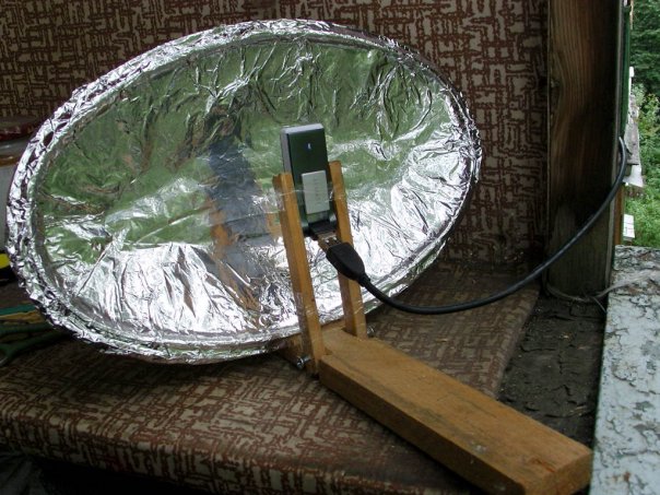
All of the methods listed above can be considered seriously only out of sporting interest, since making a parabolic reflector by hand is a very labor-intensive and expensive process. In addition, it is very difficult to accurately calculate the parameters of a satellite dish at home. Therefore, we advise you not to be original and buy a complete satellite dish.
Antenna amplifier
If the place where you live has a weak television signal and a conventional antenna cannot provide a high-quality picture on your TV, then an antenna amplifier can help in this situation. You can make it yourself if you have a little knowledge of radio electronics and know how to solder. 
Amplifiers should be installed as close to the antenna as possible. It is better to power the antenna amplifier via a coaxial cable through a decoupler.  Isolation power circuit
The decoupler is installed at the bottom of the TV and is supplied with 12 volt power from the adapter. Two-stage amplifiers consume a current of no more than 50 milliamps; for this reason, the power of the power supply should not exceed 10 watts.
All connections of the antenna amplifier on the mast must be made by soldering, since the installation of mechanical connections will lead to their corrosion and rupture during further operation in an aggressive external environment.
There are times when you have to receive and amplify a weak signal in the presence of powerful signals from other sources. In this case, both weak and strong signals arrive at the amplifier input. This leads to blocking the operation of the amplifier or switching it to a non-linear mode, mixing both signals, which is expressed in the overlay of the image from one channel to another. Reducing the amplifier supply voltage will help correct the situation.
Please note that UHF amplifiers are greatly influenced by signals in the meter range. To weaken the impact of meter signals, a high-pass filter is placed in front of the UHF amplifier, which blocks meter waves and transmits only signals in the decimeter range.
Below is a diagram of a VHF antenna amplifier:
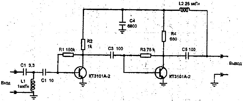
We also suggest that you familiarize yourself with the circuit of the decimeter amplifier:

You can see the operating principle of the antenna amplifier in the video:
Now, having familiarized yourself with the diagrams and armed with a soldering iron, you can safely begin making an antenna amplifier.
We hope that our article about television antennas was useful to you!