It will be useful for novice home craftsmen to learn about methods for joining wooden parts. We are devoting a short educational program to this topic, which will describe the main types of carpentry joints and joints using glue, nails, screws or dowels, or without them at all.
Rules for selecting a connection depending on the type of load
End connections are the simplest; they are used when it is necessary to extend a part. Such connections best withstand compression loads, however, when cutting locks of a special shape, good resistance to twisting, stretching and bending can be achieved. The standard version of the end connection is with trimming to half the thickness of both parts. The cut can be straight or oblique; if necessary, to prevent bending, stretching or twisting, a spike or an obtuse angle is cut at the end of each cut, or a stepped cut is made, forming a kind of “lock”.
 1 - straight half-wood overlay; 2 — oblique pad; 3 - straight overlay with a stepped joint; 4 — half-timber overlay with an oblique joint; 5 — oblique patch lock; 6 - half-tree connection with an oblique tenon
Corner and side joints are used to connect straight parts into a truss or frame. Usually this part of the structure is supporting, so the main loads occur in displacement and compression. If the structure is experiencing a static intended load, a rectangular tenon is cut on one of the parts, and a groove or eye of appropriate dimensions is cut on the other. If action on breaking the structure is possible, the tenon and groove are cut in the shape of a trapezoid.
 Corner connections: 1 - with an open through tenon; 2 - with a blind closed tenon; 3 - with a through oblique tenon
Overhead cross and T-shaped connections are used, as a rule, for additional connections between critical structural parts. The main load in them is compression, displacement and rupture. The first two types of load are eliminated by cutting half a tree or less, followed by combining the parts. The shoulders of the notches take the main load; all that remains is to secure the connection with screws or overhead staples. In some cases, to strengthen the connection, a dowel is used or a tenon with a wedge is cut out.
 1 - cross connection with a half-wood overlay; 2 — cross connection with fit into one socket; 3 - T-shaped connection with a hidden oblique tenon; 4 - T-shaped connection with a straight stepped overlay
A separate type of connection is box connection. They are intended for connecting boards at right angles. Typically, for a box joint, teeth are cut on each board, the width of which is equal to the distance between them. On different boards, the teeth are cut with an offset, so when connected, the corner of the boards looks like one whole. The teeth can also be wedge-shaped, preventing the corner from breaking in one direction, or they can be additionally secured with glue or nails.
 Box corner joints: 1 - with straight through tenons; 2 - with oblique through spikes
How to make a tenon joint
To make a tenon joint, you need to outline both parts with a marking line along all edges at a distance from the end equal to the width of the joint. On two opposite sides and the end, the body of the tenon is marked with lines; the markings on both parts are completely identical.
The tenon is cut from the sides with a hacksaw for a cross cut and the wood is chopped using a chisel. The width of the tenon is made 2-3 mm larger for subsequent precise processing with a knife or chisel. The groove is cut with a hacksaw for a longitudinal cut and chipped with a chisel, also leaving a small allowance for processing. Next comes the fitting, during which the parts are combined and the tightest fit is achieved.

With a T-shaped tenon joint, a central tenon or groove is cut on one of the parts, and an eye is hollowed out on the other, or two side trims are made, depending on the type of the first part. To make an eye, use a chisel, turning the inclined part of the blade into the hole. If the eye is not solid, I make the tenon 8-10 mm deeper and cut off its end in the shape of an expanded wedge. This way, when hammering in, the tenon will open itself and the part will be firmly seated.
To connect wide parts, you can use a box connection by cutting several tenons and grooves. The easiest way to secure a tenon joint is to drill through it across the tenons and drive a wooden dowel (window corner joint) into the hole.

How to join boards with glue
A very popular method of joining boards and bars is longitudinal and transverse gluing. When connecting boards with the wide side, the end can be smooth, although in most cases a tongue-and-groove profile is used. It is very important to tightly fit the parts so that the glue layer is as thin as possible, this is the only way to achieve maximum strength. Sometimes a small amount of cotton fiber is applied to the end, lubricated with glue, this improves the quality of the coupling.

The boards can also be joined in profile, but this will require wedge-shaped gear cutting of both ends with the teeth offset to the floor for different parts. At home, this operation can be performed using a hand router.

To glue the parts together, casein glue or high concentration PVA is used; to give strength, sifted wood flour is added to the adhesive. The surfaces are covered with glue and kept in air for 3-5 minutes, after which they are placed under pressure or squeezed with clamps. This connection is stronger than the wood itself and never breaks at the joint.
How to join elements of load-bearing structures
For load-bearing structures, two types of connections are used - extension and articulation. The easiest way to join two parts is to make a half-thick cut with a hacksaw at the same distance from the ends, and then chop off the excess wood with an ax. Once the two pieces are aligned, the joint is usually secured with two flashing strips nailed to the side of the cut. Gluing is also possible, but only if the parts fit tightly.

The ends cut into half a tree can be brought together at almost any angle; this is the main method of joining roof trusses. To fasten the parts, an additional tightening tie is required: the timber is applied to the connected parts from the side at a distance of 30-50 cm from the corner and cut to half the thickness at the points of contact, and then the structure is fastened with nails.

Often vertical and inclined structures need support, for example when connecting a rafter system to floor beams. In this case, the landing slots are cut on the horizontal beam into which the racks will be inserted. It is very important to maintain the angle of inclination and cut no more than a third of the thickness of the timber.

Connections with special connections
Almost all carpentry joints are made with additional reinforcing ties. In the simplest example, the role of these is played by nails or self-tapping screws.
When building up parts, the assembly can be strengthened with a through bolted connection, clamps, brackets and capercaillie, or it can simply be wrapped with cold-rolled wire. It is enough to fasten the spliced vertical supports with two overhead strips - wooden or metal.

Corner joints are most often secured with staples, overlay plates or angles. In cases where it is necessary to maintain a slight mobility of the connection, use one through bolt, which either stitches across the place where the parts are overlayed, or tightens them in the longitudinal direction with a minimum distance from the overlay.

The place where the special connection is attached must be removed from the edge by at least 10 diameters of the fastening element and have no defects. It is important to remember that often ties do not provide the overall strength of the connection, but only compensate for the unaccounted load.
Rafter legs can be fixed to the mauerlat or ceiling beams.
A specific decision is made taking into account the individual architectural features of the building. What differences do both methods of attaching rafters have?
| Type of rafter fastening | Performance characteristics |
|---|---|
| This method is most often used on buildings made of masonry materials and with concrete attic floors. Mauerlats are installed on the load-bearing facade walls of houses; if necessary, a special reinforcing belt is made to strengthen the supporting platform of the rafter system. Advantages: the ability to increase the height of the attic space by raising the reinforced belt around the perimeter of the building. Disadvantages: large bursting load on façade walls. |
| It is recommended to use in cases where load-bearing walls do not have high stability indicators. Rafters are attached only to beams in light frame houses made of OSB boards. Fastening to floor beams allows not only to remove thrust loads from facade walls, but also to distribute them more evenly along the perimeter of the building. Another advantage is that due to several additional stops of the rafter system, you can lighten the structure and make it more stable. This reduces the estimated cost of building a house. The floor beams can be moved beyond the perimeter of the house by a significant amount, and the support of the rafter legs on these structures increases the area of the attic space. |


There is one very important point that should be taken into account when designing this type of rafter system. The distance between the floor beams and the rafters must be the same, and this parameter depends on several factors.

The decision on the type of fixation of the rafter legs should be made by professionals at the house design stage. It should be remembered that the rafter system is considered not only one of the most important architectural elements, but also one of the most complex. Non-professionals should not undertake roof installation; such work can only be performed by experienced builders.
We will consider all possible methods of fixing elements, some of them are used extremely rarely and only during the construction of authentic houses using ancient technologies. Such work is performed by carpenters of the highest class who can work with an axe, chisel, chisel and other traditional carpentry tools.
Special metal mounting plates
Builders use two types of plates. The connection is strong and can be done quickly and without manual labor. In developed countries, house trusses are assembled on production lines, and all processes are almost completely automated. Assembly technology makes it possible to increase equipment productivity and reduce production costs. Elements of houses on the construction site are quickly assembled, the amount of manual labor is reduced to a minimum. A turnkey wooden house can be installed in just two to three weeks, depending on the number of floors and size.

What plates are used to attach rafters to beams?
Serrated
In our country, unfortunately, they are little known; in developed countries they have been used for a long time. Gear fastening - metal plates with different linear dimensions. There are teeth throughout the entire area that are driven into wooden structures. The length and distance between the teeth is selected taking into account the dimensions of the rafter legs and floor beams. This connection makes it possible to automate the production process of rafter system trusses. Toothed plates are installed on both sides of the unit being connected.

Important. Such joints on both sides can only be used on lumber with the same thickness. Maximum deviation ±1 mm. It is precisely these conditions that do not allow the widespread use of gear joints in our country; most domestic lumber does not maintain the required tolerance ranges.
The toothed plates can also be driven in by hand, but care must be taken to ensure that they are in the correct position.
Perforated
Well-known fasteners, universally usable. They can fix all elements of the rafter system and have different sizes and thicknesses. The plates are applied to the assembly, tightening is done with self-tapping screws, bolts or ordinary smooth nails. Can be mounted on one or both sides of the connection. Advantages - there are no strict requirements for the quality of lumber, a large number of holes allows you to choose the most successful places for screwing in self-tapping screws. Disadvantages - they require quite a lot of manual labor. They are harder to work with than gear ones. In addition, the installation time of the rafter system increases.


Practical advice. The strength of fastening with plates largely depends on strict adherence to the recommended technology; even minor violations can significantly reduce the stability of the rafter system. In order to eliminate the possibility of unpleasant situations occurring during the operation of buildings, practitioners recommend tightening rafters and floor beams with crossbars and using vertical racks. These elements compensate for installation errors of the rafter system, increase the time and increase the safety of home operation.

Bolted
The roofs of small utility buildings and extensions do not have significant loads; during their manufacture, simplified methods of connecting rafters and floor beams are used. The most common option is bolts. Holes are made in the floor beams and rafters, the elements are placed side by side, bolts are inserted into the holes, and the assembly is firmly tightened.

Mortise connection
More complex connection, practical construction experience required. The insertion completely eliminates the possibility of movement of the rafters at the junction with the ceiling beams; the unit is more durable and static. A recess is cut out on the beam, and a protrusion on the rafter; the parts must fit tightly into each other.
This method of fixation is done only on the house, which complicates the construction process. In addition, each connection is prepared individually, which further increases construction time and increases its cost. Another disadvantage of the tie-in is that each connection reduces the thickness of the rafters and beams, which causes a decrease in their load-bearing performance. As a result, designers must, during calculations, provide for increased dimensions of lumber, taking into account the reduction in their width as a result of sawing. And this negatively affects the cost of the building.

Notch connection
An ancient method, now used extremely rarely. The work is done by carpenters who know how to use hand tools and an axe. Notching is done only on thick rafters and beams. Using an axe, chisel and chisel, a tenon/groove connection is made at the required angle. The work is physically difficult; homemade metal staples can be used as an additional connection. The length of the staples and the diameter of the rod are selected taking into account the specific installation location and the expected maximum load.

Important. Tie-in and tapping are most often used for hanging rafter systems. Due to additional fixation, the structure can withstand significant thrust forces.
Practical tips for attaching rafters to floor beams
As an example, let’s take the most common method of fixing elements; it is suitable for all types of roofs and meets modern requirements for the strength and stability of the unit. Another advantage is that some work can be done on the ground, and only assemble ready-made structures on the building. This method of performing construction work significantly simplifies and speeds it up, and the estimated cost of the roof is reduced.
The rafters and floor beams are made of 150x50 mm boards. The rafter system is the most complex - hip multi-slope. Connecting elements are metal perforated plates. To speed up and simplify the work, it is recommended to prepare a simple, but very functional template from pieces of boards. How to make a device?
- Prepare four pieces of boards 25–30 mm thick. Two pieces approximately 20 cm long and two 40 cm long.
- Screw two short boards with corners to two long ones, leaving a gap between them equal to the thickness of the floor board. When connecting, do not join them exactly at the ends, but lift them 2–3 cm from the edge of the long ones. This protrusion serves as a support against the Mauerlat while using the template.
- At a distance of about 30 cm from the bottom, fasten the long boards together with metal perforated plates; to increase strength, on the opposite side, tighten them with boards or pieces of plywood. Make sure that the prepared template is rigid and does not wobble during use.
Such a simple device greatly facilitates the cutting of rafters to connect them to the floor beams.

How to quickly and efficiently make cuts for connections
During measurements we will use a homemade device.
Step 1. Place the device with short boards on the mauerlat, the ceiling beam should be located between them. Small protrusions in the lower part rest against the Mauerlat from the outside. The long boards are strictly vertical and are located in line with the plane of the front wall of the house.

Step 2. Screw the devices onto the Mauerlat a little, this will make further work easier. For screwing, it is better to use long and thin self-tapping screws; there is no need to tighten them completely.

Step 3. Place the rafter cut to length with its edge on the upper plane of the floor beam. The corner of the board should rest against the metal plates of the device.

The upper part of the rafter should lie in its place, in our case on the diagonal (hip) rafter leg.

After sawing, the corner of the rafter leg should lie exactly along the edge of the mauerlat. It is desirable that the floor beams occupy the same position, but some builders cannot accurately measure their dimensions. The beams come in varying lengths and are rarely located in the desired position.

Step 4. Measure the horizontal cutting line for the junction. There are two ways to do this.
- Using a building level. You can use a small tool. Draw a horizontal line from the corner of the rafter leg. Everything is simple, fast and accurate.
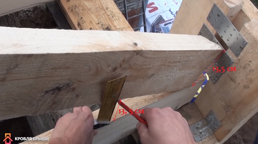
- Using a construction square. Measure the distance from the floor beam to the top corner of the rafter. Place the square on the plane of the beam and move it until the gap between the beam and the rafter is equal to the same value, in our case 13 cm. Place a mark in the right place. Connect this mark to the corner of the rafter leg. You should get a line parallel to the plane of the floor beam. Remove the board and cut off the excess piece.

The connection will be smooth, there will be no protrusions of the rafter legs. Next, you need to take measurements to cut off the upper part of the rafter leg. To do this, the lower section is put in place and held by an assistant. At the junction of the upper part of the ordinary and hip rafters, use a ruler to draw cutting lines. One at a time, press the ruler firmly against the side edges of the hip rafter and mark vertical lines on both sides.
 Apply a ruler and draw a line on the board


Important. Never mark the upper joint without filing the lower one. Some inexperienced builders mark the bottom and top of the rafters at the same time, and then cut them off. With this algorithm of work there will always be gaps; to eliminate them, the rafters will have to be shifted to the side. And this changes the step between them. The fact is that after cutting the lower joint, the angle of contact of the upper node changes.
How to prepare rafters for fastening to the ground
Real professional builders prepare almost all elements of the rafter system on the ground according to drawings or templates, number them and lift them onto the building in this form. This method of work not only speeds up the construction process significantly, but also significantly increases labor safety. Carpenters no longer need to walk on temporary flooring many times to take measurements and saw down boards; the elements are connected the first time. But in order to prepare elements on earth, you need to have extensive experience and perform the work carefully and responsibly. Houses are built abroad using this algorithm; the high labor productivity of workers explains their high earnings, in comparison with domestic ones. Let's consider the process of manufacturing the simplest trusses on the ground for connection to floor beams.
Step 1. If there are no accurate working drawings of the trusses, then a template should be made. It is made from ordinary boards approximately 25 mm thick. You need to prepare the template at home and check for accuracy in several places. The fact is that masons sometimes make mistakes, due to which the façade walls are not parallel; the spread at the corners can reach several centimeters. This defect does not affect the fastening of the rafters to the floor beams individually, but in the case of ready-made trusses, problems may arise.

Step 2. Place the template on a level area near the house. Bring the first rafter leg and lay it on one side of the truss template, align the position.

Step 3. In the same way, place the second leg on the free side of the template. Using a pencil, draw the joining lines of the rafter legs at the top of the truss. Make sure that the elements do not move during marking.


Step 4. Use a gasoline or electric saw to cut off the excess pieces of boards.

Important. At the top of the trusses, the rafter legs will be connected into half a tree; for this you need to make special cuts. You can work with a gasoline saw.
How to properly file a connection?

Practical advice. Such precise cutting can only be done with a fully functional gasoline saw with a perfectly sharpened chain. If the sharpening angle is incorrect, then the saw blade is pulled to the side and it is impossible to hold the tool straight with your hands. This saw can only be used when cutting firewood.
Step 5. Do the same operations with the second rafter. Place the cut legs on the template, check the cutting is correct, and adjust the position of the boards along the entire length of the template. Everything is fine - connect the legs of the truss at the top node. You can use ordinary nails; it's fast, cheap and reliable.


Step 6. To increase the strength and stability of the truss at the top, secure the legs with a horizontal tie. For these purposes, it is allowed to use thin boards; the element is tensile; a thickness of 20–25 mm is quite sufficient to resist loads. Tensile lumber has high strength, but problems arise when it is compressed. The boards sag, the structure completely loses stability and its original geometric shapes.


Step 7 Use a saw to cut off the lower ends of the rafter legs.

The angle on the template should be such that the connection of the elements is as tight as possible.
It is important to know that with the correct connection of the nodes of the rafter system, the strength of the structure must be maintained due to the friction forces between the elements. The boards must be pressed against each other with such force that friction does not allow them to move. What conditions must be met for this?
- First. The abutment plane should be as flat as possible, the area as large as possible.
- Second. The pressing force of the elements must be such that the friction forces reach large values.
In no case should the elements of the rafter system at the fastening points be supported only by hardware. You should always remember that they are designed to attract boards, not to hold them. All bolts are designed for tensile strength, not shear.

Bend the nails with a hammer (the truss is upside down)

We turned the truss and template over and made markings for trimming the bottom edges
As practice shows, the manufacture of roof trusses and the preparation of connection points with floor beams on the ground speeds up the roof construction process several times. The assembly itself can be fixed with metal plates on the sides, nails or bolts at the end, staples, etc. As already mentioned, to increase the stability of a rafter system of this type, it is recommended to install vertical stops between the rafters and beams.
Video - How to saw rafters at the right angle and the right size
Joints of beam elements
Features of factory, enlargement and installation joints. The need to make joints between the elements that make up the beam may arise, firstly, due to the insufficient length of sheets and angles rolled in factories compared to the length of the beam and, secondly, due to the fact that the total weight of the beam or overall dimensions it is not possible to transport or lift entire beams with the equipment available at the construction site.
In the first case, the joints of individual elements are arranged during the manufacture of the beam at the factory and are therefore called factory joints. In the second case, the joints of parts of the beams are made at enlarged installation sites, and if the carrying capacity of the installation equipment is insufficient, at the permanent location of the structure. The first of them are called enlarged joints, and the second - installation joints.
The position of the joints of individual elements made at the factory depends mainly on the length of these elements. The length of the wide sheets used for the wall, and the narrow ones that go to the belts, as well as the corners, are different, so the factory joints are arranged in different places on the beams, or, as they say, in bulk. Independent joining of individual elements during the manufacture of a beam does not cause any particular difficulties. Factory joints of sheets in the belts and walls are welded before the belt seams are applied, which ensures freedom of deformation when the joints cool, as well as ease of arrangement of the joints themselves and their subsequent processing, if required. In order to reduce the number of templates for the manufacture of individual elements, it is useful to place their joints symmetrically relative to the middle of the beam span. This creates greater repetition of elements.
Enlargement and assembly joints connect all longitudinal elements of the beam. The relative position of these elements at the time of making the joints is strictly fixed. Due to their large size and weight, rotation of the connected parts is difficult during enlarged assembly, and completely impossible during assembly. Therefore, when designing such joints, one should carefully consider the conditions of work and the availability of individual elements for welding or installing bolts (rivets).
In addition, for the convenience of transporting individual sections of beams and reducing the risk of damage to their elements, it is desirable that the latter do not form protruding parts (overhangs).
The fastening of each beam element at the joint must be designed for the force factors acting in this element (N, Q or M).
Joints in welded beams. When designing joints, it is necessary to take into account the order of welding of beam elements. This order should be such as to ensure the greatest freedom of deformation and movement of the individual elements being connected and thereby reduce the amount of shrinkage stresses. For this purpose, as noted above, factory welding of the belts and the wall is carried out separately, and then the belts are connected to the wall; in enlargement and assembly joints of beams, the waist seams do not reach the joint by approximately 50 cm (Fig. IV-18, b, c). It also shows the recommended sequence for constructing welds at the beam joint to reduce the harmful effects of shrinkage stresses.
In beams of variable section, joints of chord sheets are usually used to change their width or thickness. In a multi-sheet package, the joints of individual tapes should be spaced apart.
The most rational type and the only one acceptable in beams operating under dynamic loads is the joint of sheets without overlays (Fig. IV-18, a). Butt joints reinforced with overlays require more metal (base and weld metal), more time and labor, and the endurance limit of joints with overlays is lower than without overlays. Joints covered only with overlays have a particularly low endurance limit.
In the compressed belt of the beam, all butt seams are arranged at right angles to the longitudinal axis. If the quality of stretched butt welds can be checked by γ-ray transmission or other advanced control methods, then such seams can be made straight anywhere in the beam. If they are located in places with tensile stresses σ>0.85R, butt welds should be illuminated in the stretched belt and in the part of the wall adjacent to it at a length of about 1/10 of the wall height. If it is impossible to use increased means of control, stretched joints are arranged straight in places with stresses σ≤0.85R or oblique with an angle σ=65° between the direction of the seam and the longitudinal axis of the element (ratio of legs 2.1:1).
If a straight butt weld of a wall has a calculated tensile stress of more than Rр св = 0.85R, but the stretched belt in this place does not have a joint or its welded joint is of equal strength to the belt, then the wall seam will work under conditions of constrained deformation. Therefore, in a limited area adjacent to such a belt, you can not be afraid of the harmful consequences of design overvoltages and leave the wall seam straight.
When manufacturing beams intended for static loads, in workshops that do not have equipment for precise cutting of sheets and preparing edges for joint seams, as well as when there are large gaps between the joined parts of beams during installation, it is permissible to cover the joints of wall sheets and chords only with overlays. The joint of the wall sheets is covered with two rectangular overlays (Fig. IV-18, d), welding them with corner seams. The thickness of the wall linings is usually the same as the wall thickness. In this case, two flat frontal seams (1:1.5), laid along the long sides of the linings, have a greater load-bearing capacity than the wall:
Therefore, there is no need to install flank seams. It is difficult to arrange flank seams if belts are welded to the wall. The width of the linings is set to about 10 times their thickness (to reduce the influence of shrinkage stresses and for a smoother deflection of power flows).
The strength of the fillet welds should be checked because the length of the overlays is less than the full height of the wall.
The belts are covered with overlays. One-sided linings cause a sharp deviation of power flows and deterioration in the performance of the belts. The thickness of the overlays is determined by the required height of the fillet welds; in this case, the cross-sectional area of the lining must be no less than the cross-sectional area of the sheet being overlapped. In places where one-sided pads are attached to the belt, the height of the waist seams should be slightly increased in order to reduce the adverse effect of eccentricity at the joint.
Calculation of fillet welds attaching linings to waist sheets is carried out either by the force acting in the sheet at the joint N=Fσ, or by the load-bearing capacity of the sheet [N]=FR:
where ΣFш is the calculated area of fillet welds located on one side of the joint.
Considering the presence of eccentricity in the joint with a one-sided overlay, it is useful to increase the calculated force by approximately 20%.
The seams attaching the linings to the wall are calculated using the bending moment Mst acting in the wall:
where ΣWш is the sum of the moments of resistance of fillet welds located on one side of the joint.
The magnitude of the bending moment Mst attributable to the beam wall is determined from the proportionality between the bending moments attributable to individual parts of the composite beam and the stiffness of these parts:
where Ist, Ip and Ib are the moments of inertia of the wall, chord and the entire beam relative to the neutral axis of the beam;
Mb is the bending moment acting on the beam at the joint.
The seams connecting the linings to the wall must also be checked for the effect of shear force acting at the joint. Due to the low rigidity of the beam chords compared to the wall, it is assumed (as a safety factor) that the entire transverse force is absorbed by the seams at the wall linings. Average shear stress in seams:
where ΣFш is the sum of the areas of fillet welds located on one side of the joint.
Although the maximum stresses from shear force do not coincide with the maximum stresses from bending moment, they do conditionally check the strength of the seams under the influence of both force factors:
Beam connections
Beams can be connected to each other in a variety of ways. The choice of connection method depends on the relative position of the beams, on the force factors and on the connection means used.
Intersecting beams can be located one above the other or at the same level. In addition, adjacent beams are sometimes located obliquely in relation to the main beams in a horizontal or vertical plane.
Beam connections that transmit only support pressures are called free (hinged). Connections that transmit both support pressures and support moments are called rigid (pinched).
When designing connections between main and secondary beams, it must be taken into account that in most cases the latter are used as connections that ensure the overall stability of the main beams.
The easiest way to fasten beams is when they are located on floors.
Oblique washers should be placed from the inside under the nuts of the bolts adjacent to the flanges of I-beams and channels to eliminate the bending of the bolts in the threaded part of them.
Places where heavily loaded auxiliary beams rest on composite beams must be reinforced with stiffeners tightly fitted to the upper chord to eliminate local overstresses of the chord joints and the wall. In such cases, rolled beams should be checked for compression of the wall under the fillet connecting it to the flange. In case of overvoltage, ribs must be installed.
Connections of beams at the same level and lowered are divided into fastenings that do not require precise cutting of auxiliary beams and require precise cutting of them. The latter are very labor-intensive and therefore undesirable.
Auxiliary beams located at the same level or lower can be conveniently attached to the transverse ribs of the main beam using bolts (Fig. IV-19, a). In this case, one or both flanges of the auxiliary beams and part of the wall have to be cut off. The vertical and horizontal parts of the cut are matched by a rounding with a radius of about 20 mm. This fastening does not require precise cutting of the auxiliary beams and is convenient for installation, just like fastening the beams using a table (Fig. IV-19, b), which takes on all the support pressure.
Bolts or welds along the wall are needed to keep the auxiliary beams from tipping over and the main beam from losing stability. In the latter respect, fastening the beams to the rib is more effective than to the table.
Fastenings of freely adjacent beams are designed for support pressure A, increased by 20-30%. This takes into account the presence of minor moments in the support fastenings. If the moments are large, their influence must be taken into account in the calculation.
An example of a rigid connection of beams at one level, ensuring the transfer of not only support pressures, but also support moments, is presented in Figure IV-20. Attaching the upper chord of the auxiliary beam to the plate (called a “fish”) and the lower chord to the table must be designed for force
where M0 is the support moment of the beam,
h" - height of the auxiliary beam.
The fastening of the horizontal table to the vertical is calculated on the resultant force N and support pressure A, if the wall of the auxiliary beam is not attached directly to the main beam (Fig. IV-20, right), and on part of the support pressure A1, if the wall is attached to the main beam (Fig. . IV-20, left).
The share of support pressure - A1, transmitted through the table, and the share A2, transmitted directly from the wall to the corners, are determined under the assumption of direct proportionality between these forces and the areas of the seams securing the wall of the auxiliary beam and the console to the main beam.
The welds attaching the table to the main beam must be designed for the operating pressure A and the moment M=Ae-Nz, where e is the eccentricity of the application of force A; z is the distance from the force N to the center of gravity of the calculated welds.
An example of a rigid welded joint at a reduced level is shown in Figure IV-21. The fastening of double-walled beams is complicated by the fact that in their supporting sections there are support pressures and moments not only in the vertical plane, but also in the horizontal, as well as torques. An example of fastening a double-walled crane bridge beam to an end beam is shown in Figure IV-22. Both walls 1 of the crane beam are welded to the wall of the end beam using vertical plates 2. In the places where the walls of the crane beam adjoin the end beam, diaphragms 4 must be placed between the walls 3 of the latter. The belts of the crane beam in the assembly are replaced or covered with nodal gussets 5, expanding at an angle of 45 °. In high-speed cranes, the free edges of the nodal gussets 5 are rounded and ensure a smooth connection of the gusset edges to the chords of the connected beams. The crane beam belts can be butt welded with continuous penetration directly to the end beam belts. To stiffen the unit in this case, inserts in the shape of an isosceles triangle with a leg length and no less than the width of the wider belt of the connected beams are placed between the chords of both beams.
When calculating such connections, it is conventionally assumed that the vertical seams between the walls and the linings (w-1 and w-2) act on the vertical support pressures AB of the adjacent beam. Horizontal seams between chords and nodal inserts (w-3) act on vertical and horizontal moments and horizontal support pressures of the adjacent beam.
When calculating such connections, it is conventionally assumed that the vertical seams (w-1 and w-2) between the walls (1 and 3) and the linings (2) work to transmit the supporting vertical pressure AB of the adjacent beam. In reality, these seams also absorb some fractions of vertical and horizontal bending moments. This circumstance is taken into account by increasing the support pressure by 20-30%. When calculating the seams, it is also necessary to take into account the influence of the design moment M" = Авbн, where bн is the width of the vertical lining (the distance between the seams w-1 and w-2).
It is also conventionally believed that the horizontal seams (w-3 and w-4) between the nodal gussets and the chords of the connected beams work on the horizontal support pressure Ag of the adjacent beam (without increasing by 20-30%) and on the bending moments acting in the vertical and horizontal (Mv and Mg) planes. The total edge stresses in the weld (w-3) can be approximately checked using the formula:
where Fshz is the area of one horizontal seam (w-3) between the nodal gusset and the belt of the adjacent beam;
Wshz - moment of resistance of the same seam;
hп is the distance between the centers of gravity of the chords of the adjacent beam.
An example of the graphic design of a welded single-wall beam is presented in Figure IV-23.
Connections of wooden elements have the task of connecting mating building materials, such as edged beams, so that they do not move relative to each other. According to the position and direction of the wooden elements being connected, longitudinal connections and corner connections, as well as connections on branches and crosses, are distinguished. Spatial connecting elements made of sheet steel and plate steel plates with pre-drilled holes often replace carpenter's connections.
Connections that must transmit forces of a certain magnitude and direction, such as compressive forces, are also called joints of connected wooden elements as rods, for example compressed rods. Compressed rods connected at an acute angle can be connected using notches. Other connections of wooden structures are made by joining wooden elements using connecting means.
Based on the type of connecting means, such connections are called nail or bolt, dowel or dowel connections. In wood construction, glued building structures are also used. Because they have particular advantages, the use of laminated timber structures is of increasing importance.
Longitudinal connections
There are longitudinal connections on supports and longitudinal connections in the span. Above the supports, perpendicular trunnions, a “toe-to-foot” joint and a partially “to-toe” trunnion joint are used (Fig. 1). To reinforce these joints, flat or round steel construction staples can be driven into the top or sides. Often wooden elements are butted head-on and secured only with construction staples. If, however, there are large tensile forces at the joint, for example, at purlins on the roof rafters, then both elements are butted head-on on a support and connected by side plates made of boards or perforated strips of corrosion-protected steel.
Rice. 1. Longitudinal connections
Purlins can also be made in the form cantilever-suspended(Gerber runs) or hinged purlins. Their joint is located in a place determined by calculation, not far from the support, in which the bending moments are equal to zero and where there are no bending forces (Fig. 2). There, the purlins are connected with a straight or oblique overlay. The incoming purlin is held in place by a screw bolt, also called a hinge bolt. The hinge bolt with washers must support the load from the suspended purlin.

Rice. 2. Longitudinal connections of Gerber purlins
Gerber purlins with a joint lying on top are impractical, since there is a danger that the purlins at the edge of the joint will come off. If the joint is suspended, if damaged, there is no danger of tearing off.
To connect Gerber purlins, spatial elements made of steel sheet are also used, which are also called Gerber connecting elements. They are attached with nails to the frontal butt ends of the purlins (see Fig. 2).
Corner connections
Corner joints are necessary when two logs or beams in a corner are joined at right or approximately right angles in the same plane. The most commonly used types of joints are cut-out trunnions, smooth corner foot and compressed foot (Fig. 3). With the help of cut-out trunnions and smooth corner paws, the ends of the thresholds, purlins and rafter legs lying on supports or protruding in a cantilever are connected. Nails or screws can be used to secure connections. The compressed paw has planes that enter each other obliquely. It is particularly suitable for connecting loaded, fully supported thresholds.

Rice. 3. Corner joints
Branches
When branching, a timber suitable at a right or oblique angle in most cases is superficially joined to another beam. In ordinary cases, a joint on axles is used, and in secondary structures a “claw” connection is also used. In addition, beams made of timber can be joined using metal spatial connecting elements. In trunnion joints, the thickness of the trunnion is approximately one third of the thickness of the beam. The axles have a length in most cases from 4 to 5 cm. The groove for the axle is made 1 cm deeper so that the compression force is transmitted not through the axle section, but through the large area of the remaining cross-section of the beams.
When arranging axles, a distinction is made between normal axles that extend across the entire width of the beam, and protruding(hemp) axles, which are used for connections at the ends of beams (Fig. 4). If the beams in the connection do not approach each other at right angles, for example, with corner struts, then the axle at the strut should be made at right angles to the horizontal (or vertical) structural element (see Fig. 4).

Rice. 4. Trunnion connections
When installing axles in wooden beams and purlins, the axle must carry the entire load. It is more advantageous to carry out such connections using beam shoes made of corrosion-protected steel (Fig. 9). These shoes are secured with special nails in such a way as to prevent them from buckling and turning relative to the joint. In addition, the cross section of the beam is not weakened by the holes for the trunnions.
Cross connections
Wooden beams can intersect in one plane or with offset planes and be overhead or supporting. Beams intersecting in the same plane can intersect “IN THE PAW” if the weakening of the section does not play any role (Fig. 5). It is advisable to connect the intersecting overhead thresholds on the support beams with round dowels (pins) made of hard wood or steel with a length of 10 to 12 cm (Fig. 6).

Rice. 5. “claw” connection

Rice. 6. Connection using round keys (pins)
Side-joining beams receive good support on the pole if their connection is made “IN THE GROOT” (Fig. 7). To do this, the intersection planes of both elements are cut to a depth of 1.5 to 2.0 cm. This results in a non-shifting connection, which is secured with a screw bolt.

Rice. 7. “Groove” connection
When joining inclined and horizontal beams, as is usually the case when joining rafter legs with purlins - thresholds, a cutout is made in the rafter leg corresponding to the slope, which is called sidebar(Fig. 8).

Rice. 8. Inset of rafter leg
The depth of the mortise in the rafter legs with a normal section height of 16 to 20 cm is from 2.5 to 3.5 cm. For fastening, use one nail that penetrates the threshold for a length of at least 12 cm, or a special anchor for attaching the rafters to the purlins.

Rice. 9. Connection with steel shoe
Cuttings
When cutting, a compressed rod entering at an acute angle is connected to another beam using one or more force-transmitting planes on its front side. Based on the number and position of force-transmitting planes, a distinction is made between a frontal notch, a notch with a tooth, and a double frontal notch with a tooth.
At frontal cut(also called the frontal stop) the receiving beam has a wedge-shaped cutout corresponding in shape to the end of the compressed rod (Fig. 10). The frontal plane should pass at an angle dividing the obtuse outer corner of the notch in half. The fastening bolt must have the same direction, guaranteeing the joint against lateral displacement. To mark the notches, parallels are drawn at equal distances from the sides of the angle, which must be divided in half. The connecting line between the point of their intersection and the vertex of an obtuse angle will be the bisector of this angle (see Fig. 10). The position of the fastening bolt is obtained if the distance between the bisector and the end of the notch is divided into three parts parallel to the bisector (see Fig. 10).

Rice. 10. Frontal cut
Under the action of a compressive force, the wood lying in front of the frontal part of the compressed rod works to slice(see Fig. 10). Since the permissible stress for cutting wood along the grain is relatively small (0.9 MN/m2), the plane of the wood in front of the cut edge (cut plane) must be quite large. Since, in addition, cracking due to shrinkage should be taken into account, then, with rare exceptions, the length of the cut plane should not be less than 20 cm.
At reverse or gear notch the notch plane is cut at a right angle to the underside of the compressed rod (Fig. 11). Due to the fact that due to the eccentric connection in a gear notch there may be a risk of splitting of the compressed rod, it is necessary that the free end of the notch does not fit tightly to the support rod and that a seam is provided between them.

Rice. 11. Tooth cutting
Double cut consists, as a rule, of a frontal notch in combination with a gear notch (Fig. 12). The direction of the notch planes is similar to what is customary for each of the notches of this combination. However, the serrated notch in this case must be at least 1 cm deeper so that its cut plane is lower than the cut plane of the frontal notch. The fastening bolt should run parallel to the frontal part of the notch approximately halfway between the bisector and the top of the acute joint angle.

Rice. 12. Double cut
Cutting depth t v is limited according to DIN 1052. The determining factors for this are the contact angle (a) and the height h of the cut rod (Table 1).
Pin and bolt connections
In the case of pin and bolt connections, wooden beams or boards touching their sides are connected by cylindrical connecting elements, such as dowel rods, bolts with recessed heads and nuts, and ordinary bolts and nuts. These rod dowels and bolts are designed to prevent the wood members from moving in the joint plane, also called the shear plane. In this case, forces act perpendicular to the axis of the rod dowel or bolt. Dowels and bolts work in bending. In connecting wooden elements, all efforts are concentrated on the inner surface of the holes for dowels or bolts.
The number of rod dowels and bolts installed at the junction depends on the magnitude of the transmitted force. In this case, as a rule, at least two such elements should be installed (Fig. 13).

Rice. 13. Connection using rod dowels
In a single joint, many shear planes may be located adjacent to each other. Based on the number of cut planes, which are connected by identical connecting elements, single-cut, double-cut and multi-cut dowel and bolt connections are distinguished (Fig. 14). According to DIN 1052, single-cut load-bearing connections using dowel rods must have at least four dowel rods.

Rice. 14. Bolted connections
For bolted connections, bolts and nuts made of steel with standardized diameters of 12, 16, 20 and 24 mm are mainly used. To prevent the head and nut of the bolt from cutting into the wood, strong steel washers should be placed under them. The minimum dimensions of these washers are given for various bolt diameters in DIN 1052 (Table 2).
To prevent splintering of the connected wooden elements by the core dowels and bolts, these connecting means must be installed minimum distances between themselves, as well as from the loaded and unloaded ends. The minimum distances depend on the direction of the force, on the direction of the wood grain and on the diameter of the dowel rod or bolt db and do (Fig. 15 and 16). For load-bearing bolts and nuts, greater distances must be maintained between each other and from the loaded end than for rod dowels and bolts with hidden heads. But dowel rods or bolts with hidden heads located close to each other in the direction of the wood fibers should be spaced apart relative to the cut line so that the joints do not crack (see Fig. 15).

Rice. 15. Minimum distances for dowel rods and hidden head bolts

Rice. 16. Minimum distances in case of load-bearing bolts
Holes for pins and bolts are pre-drilled perpendicular to the cutting plane. For this purpose, electric drills with a frame with parallel movement are used. For pins, when drilling holes in wood, as well as when simultaneously drilling holes in wood and metal connecting elements, the diameter of the hole must correspond to the diameter of the pin.
Also, the holes for the bolts should be well suited to the diameter of the bolts. The diameter of the hole cannot be increased compared to the diameter of the bolt by more than 1 mm. With bolted connections, it is bad when the bolt sits loosely in the hole. It is also bad if, due to shrinkage of the wood, the clamp of the bolt in the hole gradually weakens. In this case, a backlash appears in the cut plane, which leads to even greater pressure from the bolt rod on the boundary planes of the hole walls (Fig. 17). Due to the associated flexibility, bolted connections cannot be used indefinitely. For simple buildings, such as sheds and sheds, as well as scaffolding, they can, however, be used. In any case, in the finished structure, the bolts must be tightened many times during operation.

Rice. 17. Backlash in bolted connections
Dowel connections
Dowels are fasteners made of solid wood or metal that are used together with bolts to connect smoothly joined wooden elements (Fig. 18). They are positioned in such a way that they act evenly on the surface of the elements being connected. In this case, the transmission of forces occurs only through the dowels, while the bolts provide a clamping effect in the connection so that the dowels cannot tip over. Slats made of flat or profile steel are also attached to wooden elements using dowels. To do this, use single-sided dowels or flat steel dowels. Dowels come in various shapes and types.

Rice. 18. Connecting wooden elements using dowels and bolts
When making dowel connections with pressed-in dowels, holes for the bolts are first drilled in the elements being connected. After this, the wooden elements are again separated, and a groove is cut, if necessary, for the main plate. Depending on the construction technology, the dowel is completely or partially driven into the groove of one of the elements being connected using a mallet. For final clamping of a precisely aligned connection, special clamping bolts with a large washer are used. Connections with many or large pressed-in dowels are clamped using a hydraulic press. When making connections with a large number of dowels, as is the case when making corner connections in frames made of laminated board elements, it is more preferable to use round plug-in dowels, since with pressed-in dowels the press-in pressure may be too high (Fig. 19).

Rice. 19. Dowel connection in the corner of the frame
Each dowel, as a rule, must correspond to one bolt and nut, the diameter of which depends on the size of the dowel (Table 3). The size of the washer is the same as for bolted connections. Depending on the magnitude of the force acting on the connection, larger or smaller dowels can be used. The most common diameters are from 50 to 165 mm. In the drawings, the size of the dowels is indicated by symbols (Table 4).
| Table 3. Minimum dimensions for dowel connections | ||
| Outer diameter d d in mm | Bolt diameter d b in mm | Distance between dowels/distance from dowel to the end of the element, e db, in mm |
| 50 | M12 | 120 |
| 65 | M16 | 140 |
| 85 | M20 | 170 |
| 95 | M24 | 200 |
| 115 | M24 | 230 |
| The values are valid for the family of round press-in dowels type D. | ||
| Table 4. Drawing symbols for special types of dowels | |
| Symbol | Dowel size |
| |
from 40 to 55 mm |
| |
from 56 to 70 mm |
| |
from 71 to 85 mm |
| |
from 86 to 100 mm |
 |
Nominal dimensions > 100 mm |
At placement of dowels You should maintain certain distances between the dowels and from the edges of the wooden elements. These minimum distances according to DIN 1052 depend on the type of dowel and its diameter (see Table 3).
The bolts and nuts of dowel joints are almost always passed through the center of the dowel. Only with rectangular and flat steel dowels do they lie outside the plane of the dowel. When tightening the nuts on the bolts, the washers should cut approximately 1mm into the wood. For dowel joints, the nuts on the bolts must be tightened again several months after installation, so that their tightening effect remains even after the wood shrinks. They talk about a connection with constant force transmission.
Load-bearing dowel connections
Load-bearing dowel (nail) connections have the task of transmitting tensile and compressive forces. With the help of dowel connections, load-bearing parts can be fastened, for example, for simply supported trusses, as well as structures made of boards and beams. Dowel connections can be made single-cut, double-cut and multi-cut. In this case, the size of the nails must correspond to the thickness of the lumber and the driving depth. In addition, when placing nails, certain distances between them must be maintained. In load-bearing dowel connections, holes should be drilled in advance. The drilled hole should be slightly smaller in diameter than the diameter of the nail. Since this does not cause the wood to crack as much, the nails can be placed closer together in this way. In addition, the load-bearing capacity of the nail joint will be increased, and the thickness of the wood can be reduced.
Single shear dowel connections are used when compressed and stretched rods from boards or beams must be attached to the beams (Fig. 20). In this case, the nails pass through only one connecting seam. They are loaded there perpendicular to the hole shaft and can bend if too much force is applied. Since shear forces also arise in the connecting seam in the body of the nail, this section plane is called the shear plane. In the case of paired connection of plank rods on the planes of the main beam, there are two single-cut dowel connections opposite each other.

Rice. 20. Single-cut dowel connection
At double shear dowel connections the nails pass through the three wooden elements being connected (Fig. 21). The nails have two cutting planes, since they are loaded with the same directional force in both connecting seams. Therefore, the load-bearing capacity of a double-shear loaded nail is twice that of a single-shear nail. To prevent double-cut dowel joints from coming apart, half the nails are driven in on one side, and the other half on the other. Double-shear dowel connections are mainly used if simply supported trusses consist entirely or predominantly of boards or beams.

Rice. 21. Double-cut dowel connection
Minimum thicknesses of wooden elements and minimum nailing depth
Since thin wooden elements easily split when hammering nails, the boards for load-bearing rods, belts and planks must be at least 24 mm thick. When using nails from size 42/110, use even larger ones minimum thicknessA(Fig. 22). They depend on the diameter of the nail. With dowel joints with pre-drilled holes, the minimum thickness of wood will be less than with simple nailing, since there is less risk of cracking.

Rice. 22. Minimum thickness and driving depth
The distance of the nail tip from the closest cutting plane is called the driving depth. s(see Fig. 22). It depends on the diameter of the nail dn and has a different value for single-cut and double-cut nail connections. Single shear loaded nails must have a driving depth of at least 12dn. However, for certain special nails, due to the greater holding force due to the special profiling, a driving depth of 8d n is sufficient. For double-shear connections, a driving depth of 8dn is also sufficient. With a shallower driving depth, the load-bearing capacity of the nails decreases. If nails have a driving depth of less than half the required, then they cannot be taken into account for the transmission of forces.
Minimum distances between nails
Fastening of formwork, slats and fillies, as well as rafters, sheathing, etc. acceptable using less than four nails. However, in general, a minimum of four nails are required for each seam or multiple nail joint intended to transmit forces.
The uniform arrangement of these nails on the connection plane is done using nail marks(Fig. 23). To ensure that two nails located one behind the other do not sit on the same fiber, they are shifted relative to the point of intersection of mutually perpendicular nail marks by the thickness of the nail in both directions. In addition, minimum distances must be maintained. They depend on whether the direction of force is parallel or across the fibers. Next, you need to monitor whether the ends of the rods or the edges of the wood will be loaded by the force acting in the connection or not. Since there is a danger of cracking when the ends of the rods or edges are loaded, it is necessary to maintain large distances from the edges to the nails.

Rice. 23. Minimum distances between nails for a single-cut connection
At single shear nail connection vertical or diagonal stretched rod with nails with a diameter d n ≤ 4.2 mm, the minimum distances shown in Fig. 23. When using nails with a diameter d n > 4.2 mm, these distances should be increased slightly. If nail holes are pre-drilled, shorter distances are required in most cases.
At double shear nail connections the nails are arranged in ledges. Between the risks of a single-shear nail connection, additional risks are drawn with a minimum distance of 10d n (Fig. 24).

Rice. 24. Minimum distances between nails for a double-cut connection
Installation of nail connections
When making nail connections, the nails must be driven vertically into the wood. In this case, the nail head should only be slightly pressed into the wood so that the wood fibers at the joint are not damaged. For the same reason, the protruding ends of the nails can only be bent in a special way. This should only occur perpendicular to the grain. To apply the location of nails, as a rule, appropriately drilled templates made of thin plywood or tin are used. In the case of plywood templates, the holes are made of such a diameter that the heads of the nails can pass through them. In the case of templates made of tin, the locations of the nails are marked with a brush and paint.
Nail connections with steel plates
Nail connections with steel plates can be divided into three types, namely connections with embedded or externally lying plates with a thickness of at least 2 mm and connections with embedded plates with a thickness of less than 2 mm.
Externally lying pads, as a rule, have pre-drilled holes (Fig. 25). They are placed over the joint of beams or boards at the end and nailed with the appropriate number of wire or special nails. At embedded overlays with a thickness of at least 2 mm nail holes must be drilled simultaneously in the wood members and in the trims. In this case, the diameter of the holes must correspond to the diameter of the nail. Embedded overlays with thickness less than 2 mm, of which there may be several at the joint, can be pierced with nails without pre-drilling (Fig. 26). Such connections can only be made using specially designed spline tools and only with special approval from the authorities.

Rice. 25. Connection using a perforated steel plate-plate

Rice. 26. Nail connection with embedded steel plates (Greim)
Connections using nail gussets
Nail gussets are used for the rational production of wooden half-timbered trusses from single-row sections of wood (Fig. 27). To do this, wooden rods of equal thickness are cut to length, impregnated and adjusted exactly to each other.

Rice. 27. Connection using a nail gusset
The moisture content of the wood should not exceed 20%, and the difference in thickness should not be more than 1 mm. In addition, the rods should not have any cuts or edges.
The nail gussets must be placed symmetrically on both sides and, using a suitable press, pressed into the wood so that the nails sit in the wood to their full length. Driving nail heads using a hammer or the like is not permitted.
Fastening with nail gussets creates a connection or joints that are strong in compression, tension and shear at nodal points without weakening the load-bearing section of the wood. For the transmission of forces, the main importance is the working area of the connection of the nail gusset (Fig. 28). It corresponds to the area of contact of the nail gusset with the wood, with the exception of the edge strip with a width of at least 10 mm.

Rice. 28. Working area of the connection at the nail gusset
Trusses with gusseted connections of rods are industrially manufactured only by licensed enterprises, delivered ready-made to the construction site and installed there.
Whether you are using wooden beams in the interior of a house, making a roof, or perhaps building a terrace, you will need information on how to connect wooden beams.
If earlier connections were made using spikes, then this old-fashioned method is gradually becoming a thing of the past; perhaps professionals still use it, but most likely in the near future they will begin to use more modern approaches.
Indeed, in our time, metal connectors allow you to quickly and reliably connect wooden beams. This is in contrast to screwing, which is also only suitable for certain types of connections, such as diagonal braces. Today, connectors for wooden beams are available for almost any connection option.
The connectors are made from sheet steel and are pre-drilled. Smaller 3.5mm or 4.5mm holes work great for galvanized V or comb nails. Some fittings also have larger holes with a diameter of 11 or 13.5 mm. They are used for hex head screws.
Below we will explain which and where fittings are suitable for connecting wooden beams.
1. T-joints for wooden beams
If you want to connect a beam with a transversely standing beam or, conversely, to connect a vertically standing beam with a horizontal one, you can make such a connection in several ways:
Straight connectors range from 96mm to 180mm in length (pictured left) and are secured with nails or screws.
There are even large straight connectors with lengths of up to 400 mm or even up to 1250 mm - allowing long distances to be attached to the beam.
T-connectors, also called cross connectors, are suitable for 3-beam T-joints (2 cross-beams laid side by side next to each other on the same post). Typically these types of connections are used when constructing sheds or terraces.

Such fastenings are used primarily when it is necessary to further stabilize rectangular beam connections. They are installed at an angle of 135°; for mounting at other angles, an adjustable angle connector is used.
Alternatively, you can use universal connectors (multi-function connectors) with slotted thigh ends. These connectors have a predetermined bend point so that they can be adapted to any required angle. Thus, these beam connectors can be used in a wide variety of ways.

Rafter connections are used primarily for roofing structures. Particularly strong beam connections are required here, as they are often exposed to strong winds.
These strong connections are achieved using rafter connectors, which are available in six standard sizes. Such products are made in two types - right and left - so that the beam can be secured on both sides.

Beam shoes are used when connecting a beam to a main beam. These connections are, in particular, the most common when arranging the interior of a room using beams.
This is a particularly strong connection, which is used not only to connect beam to beam, but also beam to concrete, brick, or metal.
Such connectors are available in various designs: for external fastening - type A, for internal fastening - type B. The second type allows you to make a more invisible connection, but has less torsional rigidity than the first type.
A beam-to-beam connection that does not comply with standard dimensions can be realized using a two-piece connector - Vario (type C).
5. Corner connectors for wooden beams

Corner connectors or corner sheets are primarily suitable for rectangular wooden joints that will not be subject to heavy loads. Therefore, they are often used in the manufacture of furniture and interior decoration.
Corner connectors are available in various sizes and designs, for example as a corner with perforated plate or with longitudinal holes. So they can be very versatile.
To ensure greater stability, special heavy-duty connectors must be used.

Cross connectors are used, for example, in the construction of pergolas. To secure this type of beam connection, connectors are available in several options.
For perpendicular beam connections, connectors of the first type are very suitable (see figure). For inclined cross connections, male connectors can be used. A slightly more complex option, but also possible, is the use of connectors with two corners (point 5) for heavy loads.